Electrical connector devices and methods for employing same

a technology of electrical connectors and connectors, applied in the direction of coupling contact members, coupling device connections, contact members penetrating/cutting insulation/cable strands, etc., can solve the problems of further limitation in this area, and the limitations of products such as thes

Active Publication Date: 2006-01-31
CONNECTING PRODS
View PDF6 Cites 19 Cited by
  • Summary
  • Abstract
  • Description
  • Claims
  • Application Information

AI Technical Summary

Benefits of technology

[0011]It is an object of the present invention to provide an electrical connector that will establish an effective, gas tight electrical connection between the connector and a wire.

Problems solved by technology

Also, products such as these are limited in how well they make a mechanical and electrical connection with a wire.
They are further limited in this area by the diameter of the wire being connected.

Method used


Image

  • Electrical connector devices and methods for employing same
  • Electrical connector devices and methods for employing same
  • Electrical connector devices and methods for employing same

Examples


Embodiment Construction

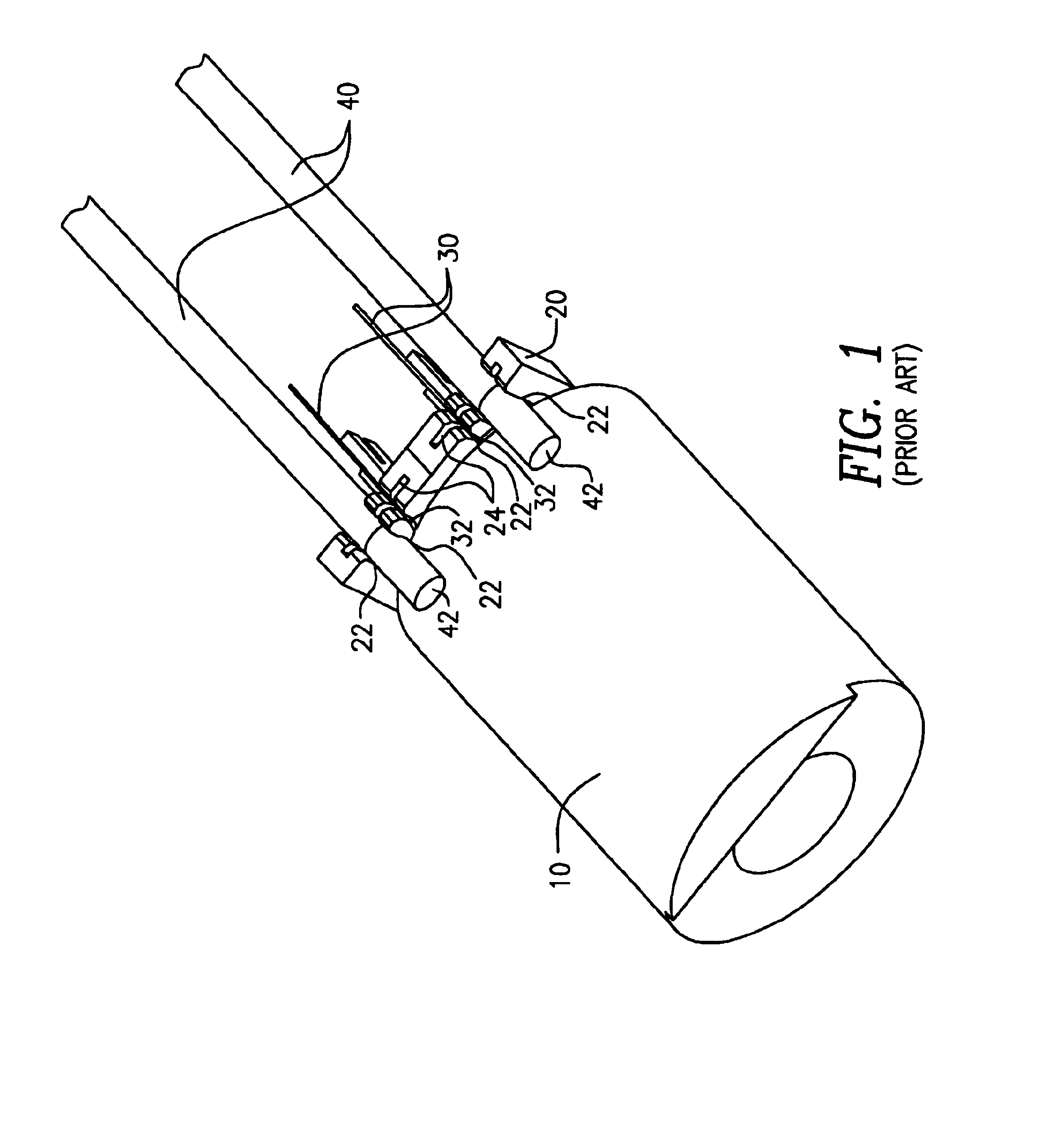
[0045]FIG. 1 is a representation of a simple coil 10 wound on a bobbin 20. Bobbin 20 further comprises integrated pockets 22 and slots 24. The ends 32 of the magnet wire 30 winding are pre-positioned and anchored in their appropriate slots 24. The ends 42 of the lead wires 40 are also pre-positioned in their slots 24. Slots 24 hold the wires in exact positions across pockets 22. Pockets 22 are adapted to support the wires while a connector 100 is introduced into them, as illustrated in FIG. 3.

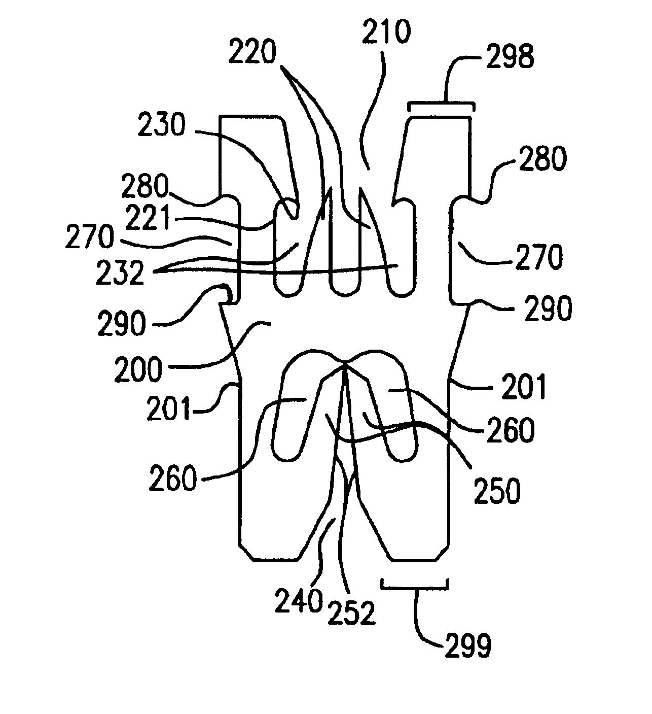
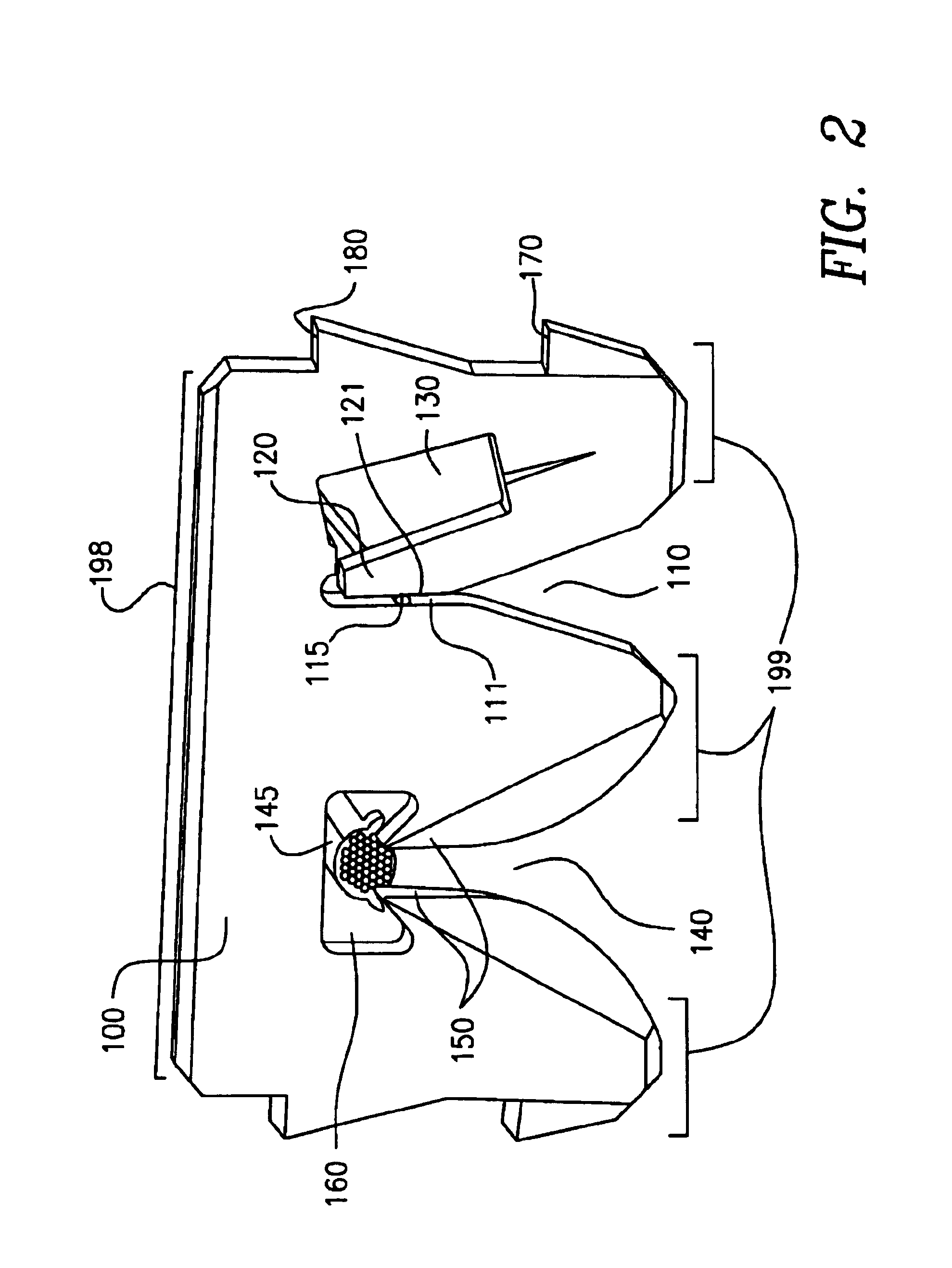
[0046]Electrical connector 100 is preferably a planar piece of conductive material, usually metal. Now referring to FIG. 2, a preferred embodiment of a metal connector 100 is disclosed, typically produced by progressive die stamping, as is known in the prior art. Slot 110 is configured to accommodate magnet wire 115 and slot 140 is configured to accommodate lead wire 145. Slot 110 comprises a small cantilever blade 120, which keeps a spring load on magnet wire 115 as the slot slides across the ...


PUM


Abstract

An electrical connector for connecting two or more wires together electrically, having wire slots are oriented in a direction substantially parallel to each other, facilitating the use of only one operation to connect all wires; also retaining a terminated wires. Also methods for producing such connector, minimizing waste of production material, using such connector and configuring such connector at small dimensions and tolerances.

Description

[0001]This application claims the benefit of U.S. Provisional Patent Application Ser. No. 60 / 413,362, filed Sep. 25, 2002.BACKGROUND OF THE INVENTION[0002]Magnet wire is a single strand wire is typically used whenever a coil is built, and in a variety of other applications. Typically it is covered by a relatively thin film of insulation, which serves to insulate the wire from adjacent wires. Magnet wire can be very thin, ranging in diameter to 0.010″, if not even thinner.[0003]Lead wire is used to convey larger amounts of electricity over longer distances, such as from a power source to a coil. A lead wire is typically a multi-strand conductor for flexibility and is covered by a relatively thick layer of insulation. A standard configuration for lead wire is 10 conductor strands, each measuring 0.010″ diameter, and covered by insulation. The entire lead wire typically has a diameter of about 0.100″.[0004]Bare wire is among the most basic of wires. It is merely a single strand conduct...

Claims


Application Information

Patent Timeline
Patent Type & Authority Patents(United States)
IPC IPC(8): H01R11/20H01R4/24
CPCH01R4/2425
Inventor FREAKES, ANTHONY
Owner CONNECTING PRODS
Why Eureka
Try Eureka