Implantable pump

a technology of implantable pumps and ridges, which is applied in the field of implantable pump assemblies, can solve the problems of insufficient tissue space, insufficient tissue purchase, and the continuous nature of grooves and ridges, and achieve the effects of less rounded tips, improved protruding and ridge systems, and greater tissue purchas

Inactive Publication Date: 2006-01-31
BOSTON SCI SCIMED INC
View PDF106 Cites 51 Cited by
  • Summary
  • Abstract
  • Description
  • Claims
  • Application Information

AI Technical Summary

Benefits of technology

[0015]In one aspect, the present invention includes an improved protrusion and groove system for an implantable pump. The protrusion and groove system affords space for tissue to extrude into and surfaces to block movement of the implant relative to tissue in three mutually perpendicular directions. In preferred embodiments, the protrusions are discontinuous and have edges that block movement in a direction substantially parallel to a longitudinal axis of the grooves. Also preferably, the protrusions have less rounded tips than prior art ribs to afford greater tissue purchase and a firmer grasp of the implantable pump.

Problems solved by technology

However, there is no structure blocking movement of tissue relative to the pump along a longitudinal axis of a groove.
The continuous nature of the grooves and ridges is believed to present a problem.
This is undesirable as squeezing tissue into the grooves is believed to help anchor the pump to the tissue during the act of squeezing. FIG. 1A depicts ribs of a prior art Alpha device.
This small area is not optimal for affording tissue to extrude between the ribs when the patients squeezes tissue to compress the pump bulb
This is also believed to be a problem as the rounded tips do not afford optimal tissue purchase and can result in tissue sliding off the tip of the ridge.
The size of the pump limits the pressure that can be transmitted to the cylinders and therefore limits the stiffness of the cylinder.
Again, these ribs are rounded and slippery.

Method used


Image

  • Implantable pump
  • Implantable pump
  • Implantable pump

Examples


Embodiment Construction

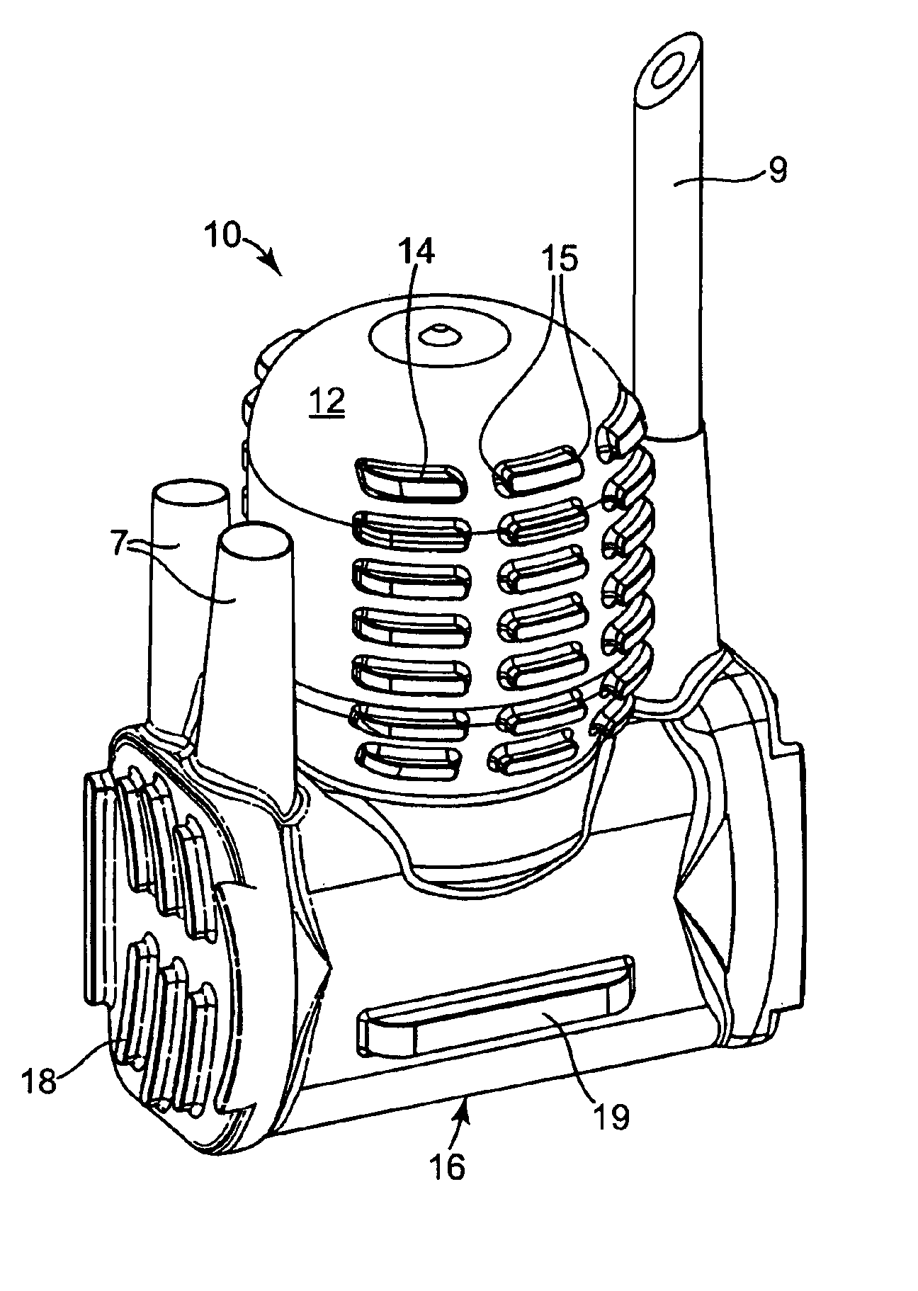
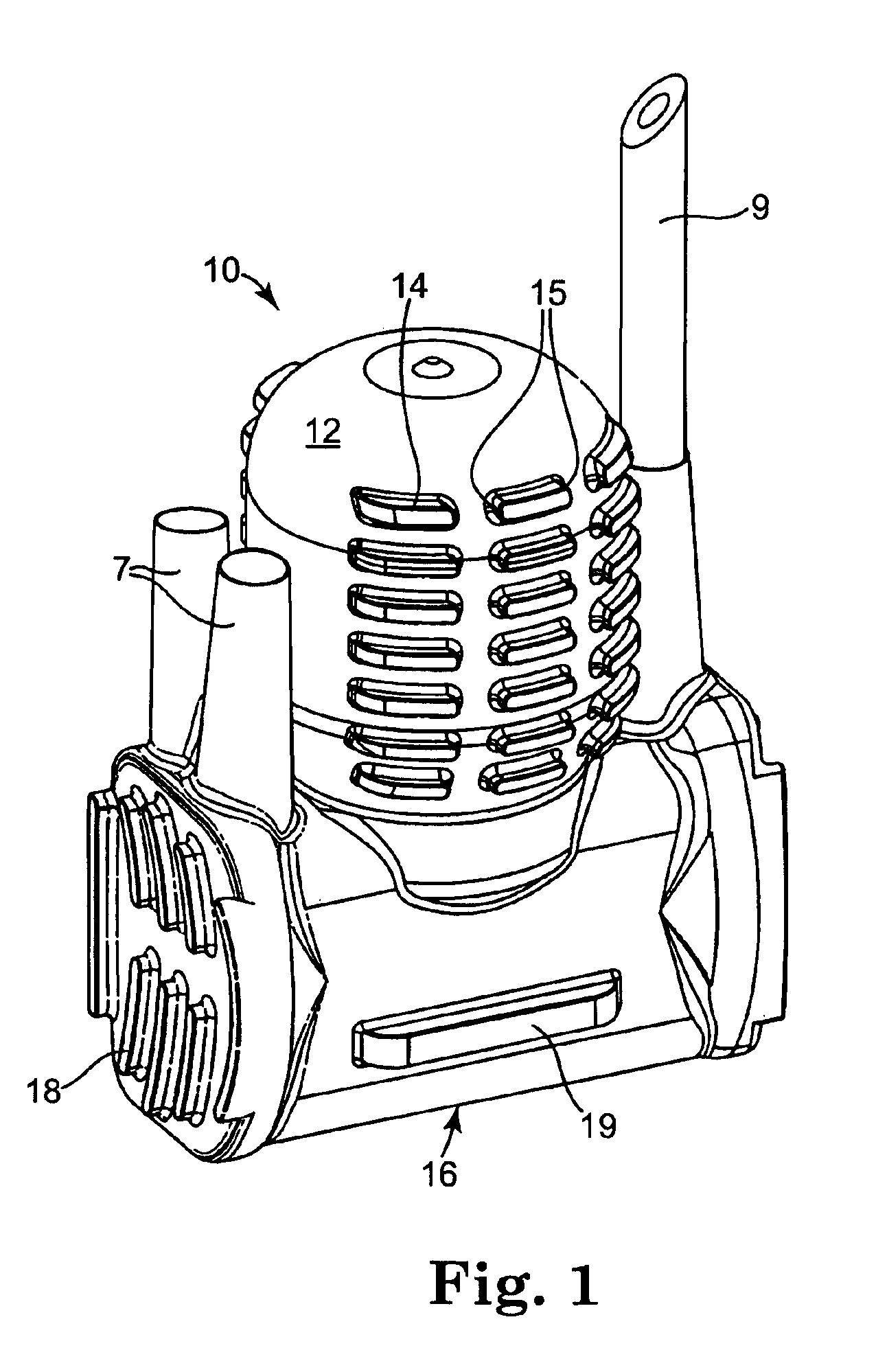
[0066]Referring to FIGS. 1 through 6, there is shown an embodiment of pump assembly 10 according to an aspect of the present invention. The pump assembly 10 includes a pump bulb 12 having a plurality of protrusions 14 with a longitudinal axes L (FIG. 2). The protrusions 12 are spaced apart by a plurality of grooves G with longitudinal axes A. Preferably, the protrusions 14 have ends 15 that separate the protrusions 14 from each other.

[0067]The pump assembly 10 is adapted to be in fluid communication with a reservoir via tube 9. The pump assembly 10 is adapted to be in fluid communication with implantable inflatable members via tubes 7.

[0068]The protrusion ends 15 form channels C having longitudinal axes A′ extending at angles relative to the longitudinal axes A of the grooves G. Preferably the angle is approximately ninety degrees, but other angles are also contemplated herein. Also preferably, the ends 15 face each other across channels C.

[0069]The protrusions 14 facilitate tractio...


PUM


Abstract

An implantable pump with a plurality of protrusions and grooves is described.

Description

REFERENCE TO RELATED APPLICATIONS[0001]This application claims the benefit of provisional application Ser. No. 60 / 430,200 which was filed Dec. 2, 2002.BACKGROUND[0002]This invention generally relates to an implantable pump assembly for inflating a prosthesis. More particularly, the invention relates to a pump assembly for an inflatable penile prosthesis.[0003]One common treatment for male erectile dysfunction is the implantation of a penile prosthesis. Such a prosthesis typically includes a pair of inflatable cylinders which are fluidly connected to a fluid (typically liquid) reservoir via a pump and valve assembly. The two cylinders are normally implanted into the corpus cavernosae of the patient and, in some embodiments, a reservoir may be implanted in the patient's abdomen. The pump assembly is implanted in the scrotum. During use, the patient actuates the pump and fluid is transferred from the reservoir through the pump and into the cylinders. This results in the inflation of th...

Claims


Application Information

Patent Timeline
Patent Type & Authority Patents(United States)
IPC IPC(8): A61F5/00A61F2/26
CPCA61F2/26
Inventor KUYAVA, CHARLES C.MORNINGSTAR, RANDY L.ROWLAND, RANDALL P.ROCHELEAU, GARY A.
Owner BOSTON SCI SCIMED INC
Why Eureka
Try Eureka