Screen cloth insertion apparatus and method

a technology of screen cloth and insertion apparatus, which is applied in the direction of insect protection, door/window protective devices, bandages, etc., can solve the problems of screen bars deformation inwardly, not only aesthetically undesirable, but also prevent proper installation in the window opening

Inactive Publication Date: 2006-01-31
SAINT GOBAIN BAYFORM OF AMERICA
View PDF61 Cites 31 Cited by
  • Summary
  • Abstract
  • Description
  • Claims
  • Application Information

AI Technical Summary

Problems solved by technology

However, if the screen is tensioned excessively, the screen bars deform inwardly in an hourglass shape.
This resultant shape is not only aesthetically undesirable, but also can prevent proper installation in the window opening.
Excess screen tension also increases the risk of tearing the screen during manufacture of the screen and frame assembly or while the assembly is in service.
However, this automation has proven to be very difficult and machines of this nature have not been widely accepted as a viable option to hand wiring.
If the screen bar is not constrained, when the spline is inserted into the screen bar, excessive tension may be placed on the frame, causing the frame to hourglass inwards.
Ideally, no excess screen is used, but this is difficult to achieve in practice.
Any out-of-tolerance spline and screen bar produced costs the manufacturer in wasted time, material and goodwill.
Further, the amount of force required by an installer to secure the screen with the spline in the spline groove may be high enough to cause repetitive strain injury, e.g., carpal tunnel syndrome, to one who routinely performs this job.
Further, such an injury to an installer is also costly to the manufacturer in terms of compensation and loss of skilled labor.
Also, the hand wiring technique is particularly difficult and time-consuming.
Notably, it is difficult to control the wire-like spline material and simultaneously control the screen tension with one hand, while the spline is rolled in with the other hand.
This adds to the final manufacturing cost, and, hence, increases the final cost to the consumer.
Final product consistency is difficult to maintain.
Quality control also has become an issue with current spline techniques.
However, this also reduces the “pull-out” force or attachment strength of the spline and screen.
The result is that the screen can be more easily pulled out from the spline groove, which is undesirable.
There are other drawbacks associated with conventional spline techniques.
In particular, the use of a separate fastening device, such as a spline, requires separate inventory control and associated costs.
Also, the need to have a strong interference fit in securing the spline necessitates stiff walls on the spline groove.
Further, the spline technology makes the design of automatic assembly equipment extremely complex.
This method, however, requires external tensioning until the thermoplastic cools and solidifies.
This complex technique requires high manufacturing precision, including proper tensioning of the screen and mating of the heating elements and the tensioning frame.
Further, this technique is too slow and cumbersome to be considered practical for the manufacture of screen and frame assemblies for windows and the like.
The exotic techniques for the small parts, as described in the '065 patent and the '828 document, are generally limited to their particular applications.

Method used


Image

  • Screen cloth insertion apparatus and method
  • Screen cloth insertion apparatus and method
  • Screen cloth insertion apparatus and method

Examples


Embodiment Construction

[0083]PCT International Application No. PCT / IB00 / 01716, filed Aug. 23, 2000, U.S. patent application Ser. No. 09 / 379,102 filed Aug. 23, 1999, and U.S. patent application Ser. No. 08 / 997,737 filed Dec. 24, 1997 are all expressly incorporated by reference herein in their entireties.

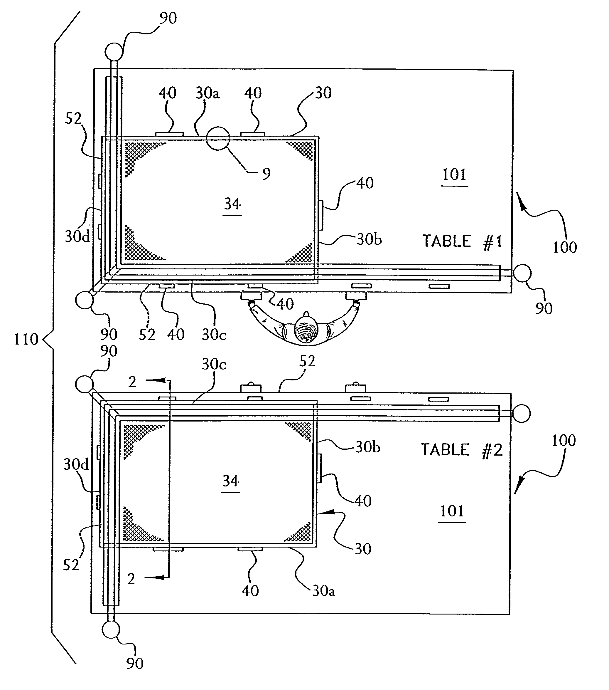
[0084]The invention includes a method and apparatus for securing a screen 34 to a frame 30, or to a screen bar segment 30a of the frame 30. The invention also includes a frame and screen assembly formed by the method, and a screen bar stock used in the assembly.

[0085]As shown in FIG. 1, the exemplary frame 30 includes a plurality of screen bar segments 30a–30d. Each screen bar segment 30a–30d has a mounting surface 32a which may be a bottom of a groove or tensioning step 32 or 32′ (best seen in FIGS. 6–11) on a face of the frame 30. The frame 30 may have a flat face, and the mounting surface may be a portion of the flat surface (not shown), but a groove 32 or tensioning step 32′ is preferred, because it enh...


PUM

PropertyMeasurementUnit
lengthaaaaaaaaaa
lengthaaaaaaaaaa
widthaaaaaaaaaa

Abstract

An apparatus secures ventilation cloth to a screen frame. A screen frame is oriented in an approximately vertical position. The screen frame has a plurality of segments. Each segment has a mounting surface on a face thereof. At least one of said segments has adhesive on the mounting surface thereof. A ventilation cloth is hung across the mounting surface of said one segment. The adhesive in said one of the segments is melted. The ventilation cloth is inserted in the adhesive across a length of said one of the segments.

Description

[0001]This application is a continuation-in-part of International Application No. PCT / IB00 / 01716, filed Aug. 23, 2000, which is a continuation-in-part of U.S. patent application Ser. No. 09 / 379,102 filed Aug. 23, 1999, now U.S. Pat. No. 6,331,223 B1, which is a continuation-in-part of U.S. patent application Ser. No. 08 / 997,737 filed Dec. 24, 1997, now U.S. Pat. No. 6,279,644 B1. This application claims the benefit of U.S. Provisional Patent Application No. 60 / 272,334, filed Feb. 28, 2001.FIELD OF THE INVENTION[0002]The present invention relates to a screen and frame assembly for windows, doors and the like, and methods and apparatus for fabricating such frame assemblies.BACKGROUND OF THE INVENTION[0003]The general purpose of screens is to prevent the ingress of insects, while providing ventilation. A typical screen assembly is made up of screen cloth, fabric, or mesh attached to a screen frame in a manner discussed in more detail below. For brevity, the term “screen” is used herein...

Claims


Application Information

Patent Timeline
Patent Type & Authority Patents(United States)
IPC IPC(8): E06B9/00E06B9/52
CPCE06B9/52Y10T156/1052
Inventor WYLIE, DOUGLAS H.WALKER, JOHN A.NELSON, DAVID G.RAVINDRAN, SAJ
Owner SAINT GOBAIN BAYFORM OF AMERICA
Why Eureka
Try Eureka