Current sensing circuit for DC/DC buck converters

a current sensing circuit and converter technology, applied in the direction of electrical equipment, electrical variable regulation, instruments, etc., can solve problems such as loss of efficiency, and achieve the effects of short settling time, good stability against process variations, and minimal efficiency loss

Active Publication Date: 2006-01-31
DIALOG SEMICONDUCTOR GMBH
View PDF14 Cites 11 Cited by
  • Summary
  • Abstract
  • Description
  • Claims
  • Application Information

AI Technical Summary

Benefits of technology

[0012]A principal object of the present invention is to achieve a current sense circuit for DC / DC buck converters with minimal efficiency loss, short settling time and good stability against process variations.
[0013]Another further object of the present invention is to achieve a method to sense efficiently the current of DC / DC buck converters.

Problems solved by technology
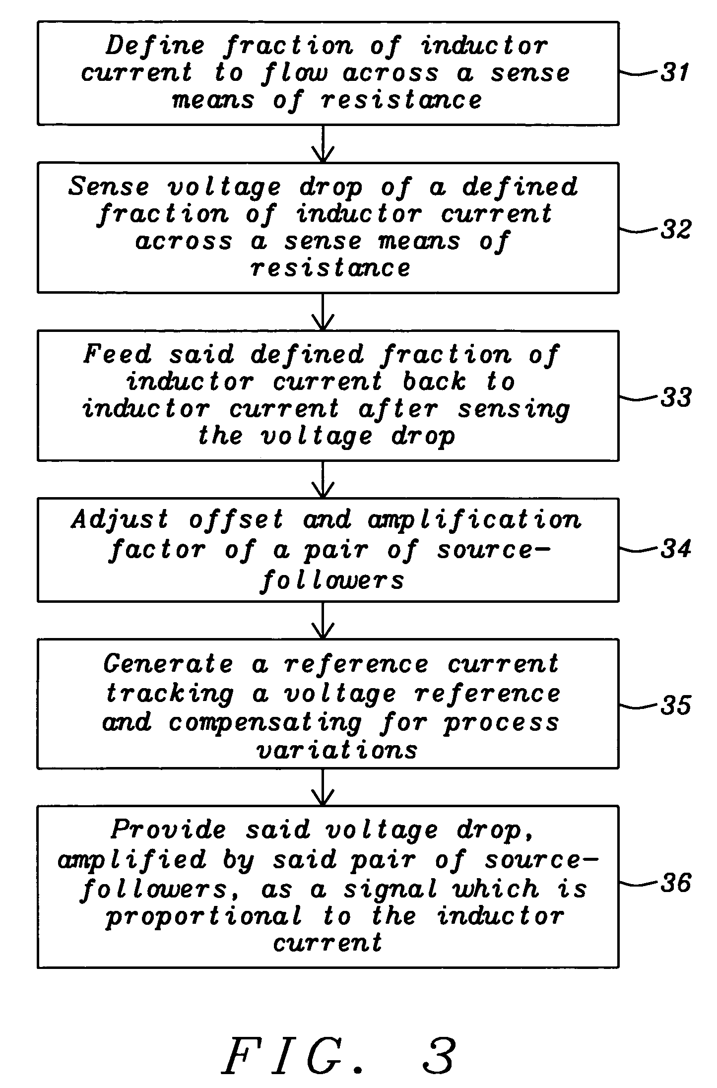
It is a challenge to the designers of such circuits to establish a current sensing circuit with a minimum efficiency loss, short settling time and good stability against process variations.
The first method requires an additional external component and the loss of efficiency is given by the waste of power in the shunt resistor.

Method used


Image

  • Current sensing circuit for DC/DC buck converters
  • Current sensing circuit for DC/DC buck converters
  • Current sensing circuit for DC/DC buck converters

Examples


Embodiment Construction

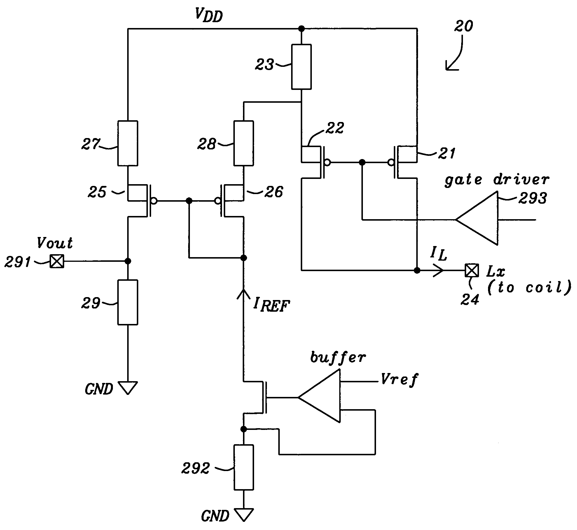
[0020]The preferred embodiments disclose a circuit and a method to sense the current through a transistor power switch and through the inductor of a DC-to-DC buck converter. It should be clear to those experienced in the art that the present invention can be applied and extended without deviating from the scope of the present invention.

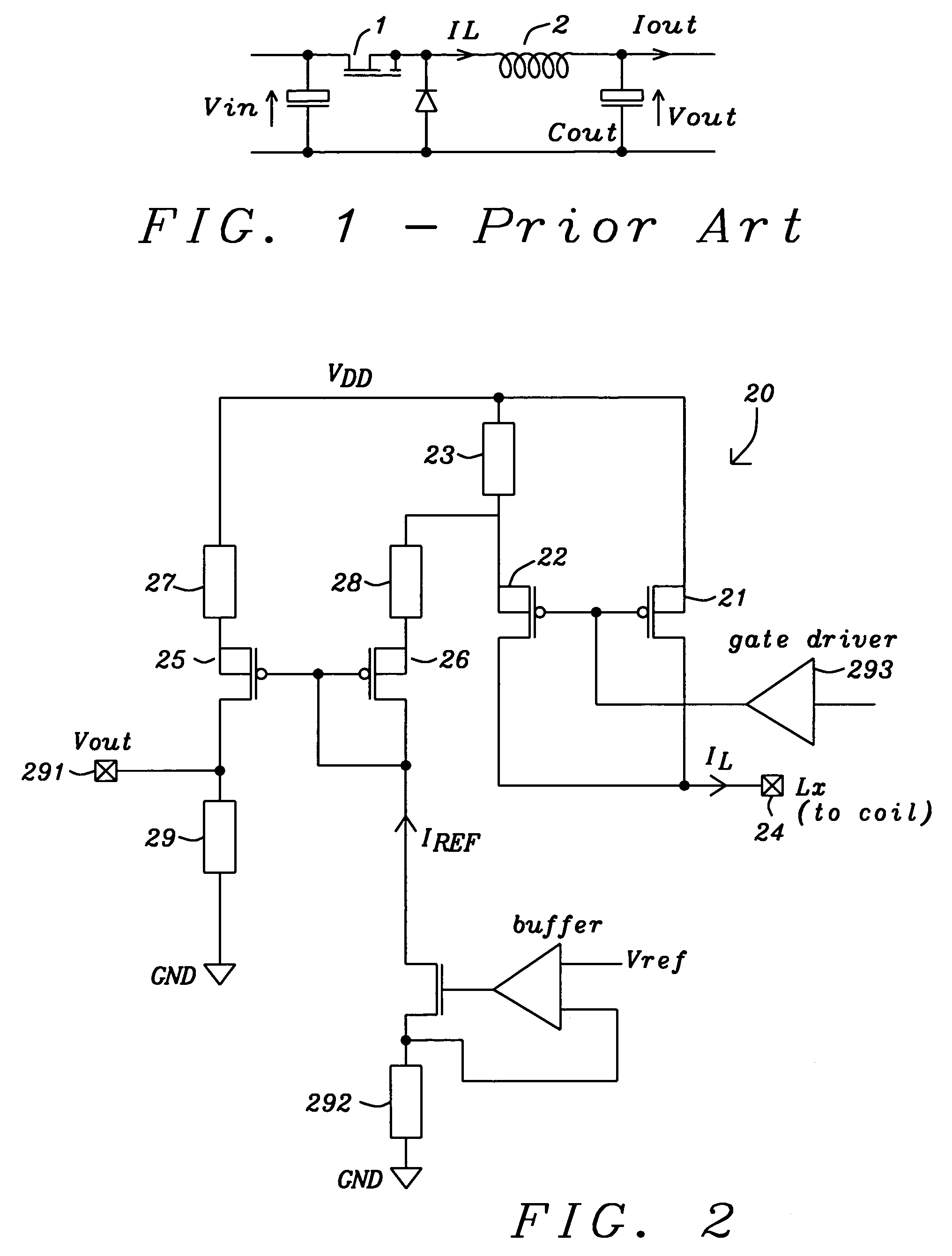
[0021]Referring now to FIG. 2 an embodiment of a circuit of the present invention is illustrated. The current sensing circuit 20 of a DC / DC buck converter is performed by adding a PMOS source follower 22 to the PMOS pass device 21. A sense-resistor 23 is connected to the source of the source follower 22 and to the source of the pass device 21 and to the main supply voltage VDD. The source of the pass device is also connected to VDD. The drain of the pass device 21 and the drain of the source follower 22 are connected to a pin 24, which is connected to the external inductor (coil) of the DC / DC buck converter. The gate driver 293 defines the operation p...


PUM


Abstract

A circuit and a related method to sense the inductor current of CD / DC buck converters have been achieved. The inductor current is sensed by generation of a voltage drop across a fully integrated sense resistor. The voltage drop is proportional to the inductor current in the pass device by supplying a fraction of the inductor current out of a source-follower, which matches to the pass device. The source of said source-follower is connected to a sense-resistor that is connected to the same supply as the pass device. The current, which is needed to generate the voltage drop, is fed back into the inductor current minimizing therefore the efficiency loss. Mirroring, amplification and offset correction of the voltage drop across the sense-resistor is performed by using a single matching pair of source-follower, which is supplied by a current tracking the internal reference voltage and the process variations of the resistors.

Description

BACKGROUND OF THE INVENTION[0001](1) Field of the Invention[0002]The present invention relates generally to voltage control unit circuits, and more particularly, to a current sense circuit for DC-DC buck converters.[0003](2) Description of the Prior Art[0004]Current sense circuits are widely used in integrated circuits. If a potentially large output current, or load current, must be driven by an on-chip switch, a current sense circuit may be used to detect the relative or absolute value of this current. The current level may be monitored to prevent damage to the switch, or to the integrated circuit from either a short circuit or a simple overloading.[0005]A buck converter converts an input voltage to a lower output voltage. Referring now to FIG. 1 prior art, a simplified schematic of a DC / DC buck converter is illustrated. The transistor 1 works as a switch, which is driven by a high frequency pulse-width-modulated control voltage. The switch is turned on and off by the pulse-width-m...

Claims


Application Information

Patent Timeline
Patent Type & Authority Patents(United States)
IPC IPC(8): G05F3/16G05F1/40G01R19/00H02M3/156
CPCG01R19/0092H02M2001/0009H02M3/156H02M1/0009
Inventor MARSCHALKOWSKI, ERICMALCOLM, JOHN
Owner DIALOG SEMICONDUCTOR GMBH
Why Eureka
Try Eureka