
Terminal adapter for connecting a terminal to a computer local area network capable of identifying any of several terminal types

a terminal adapter and terminal technology, applied in the direction of program control, instruments, testing/monitoring control systems, etc., can solve the problems of limiting the freedom of movement of persons, more difficult installation of local area networks, and creating electrical hazards, so as to achieve no risk

Inactive Publication Date: 2006-01-31
ALCATEL LUCENT SAS
View PDF9 Cites 17 Cited by
  • Summary
  • Abstract
  • Description
  • Claims
  • Application Information

AI Technical Summary

Benefits of technology

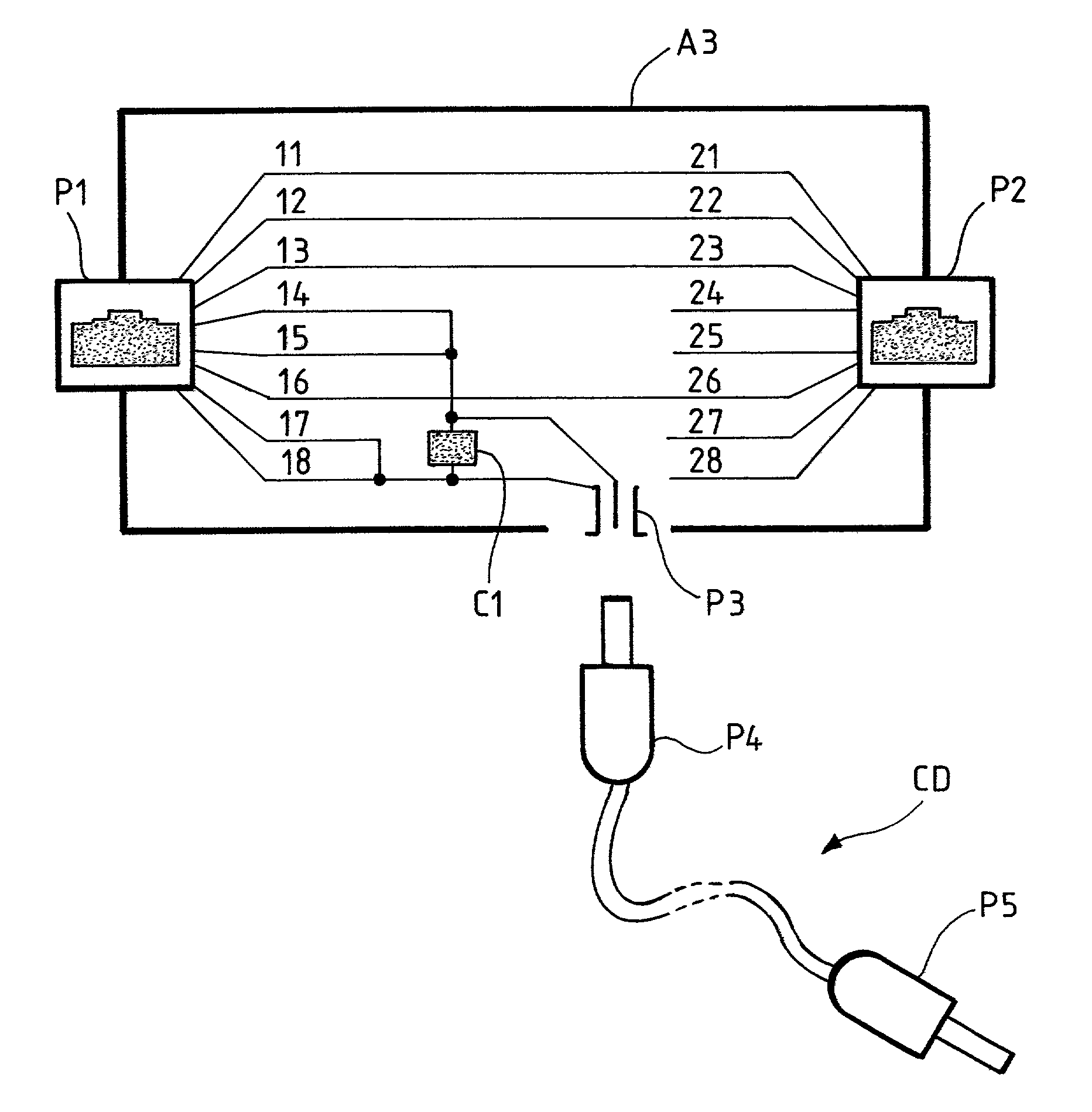
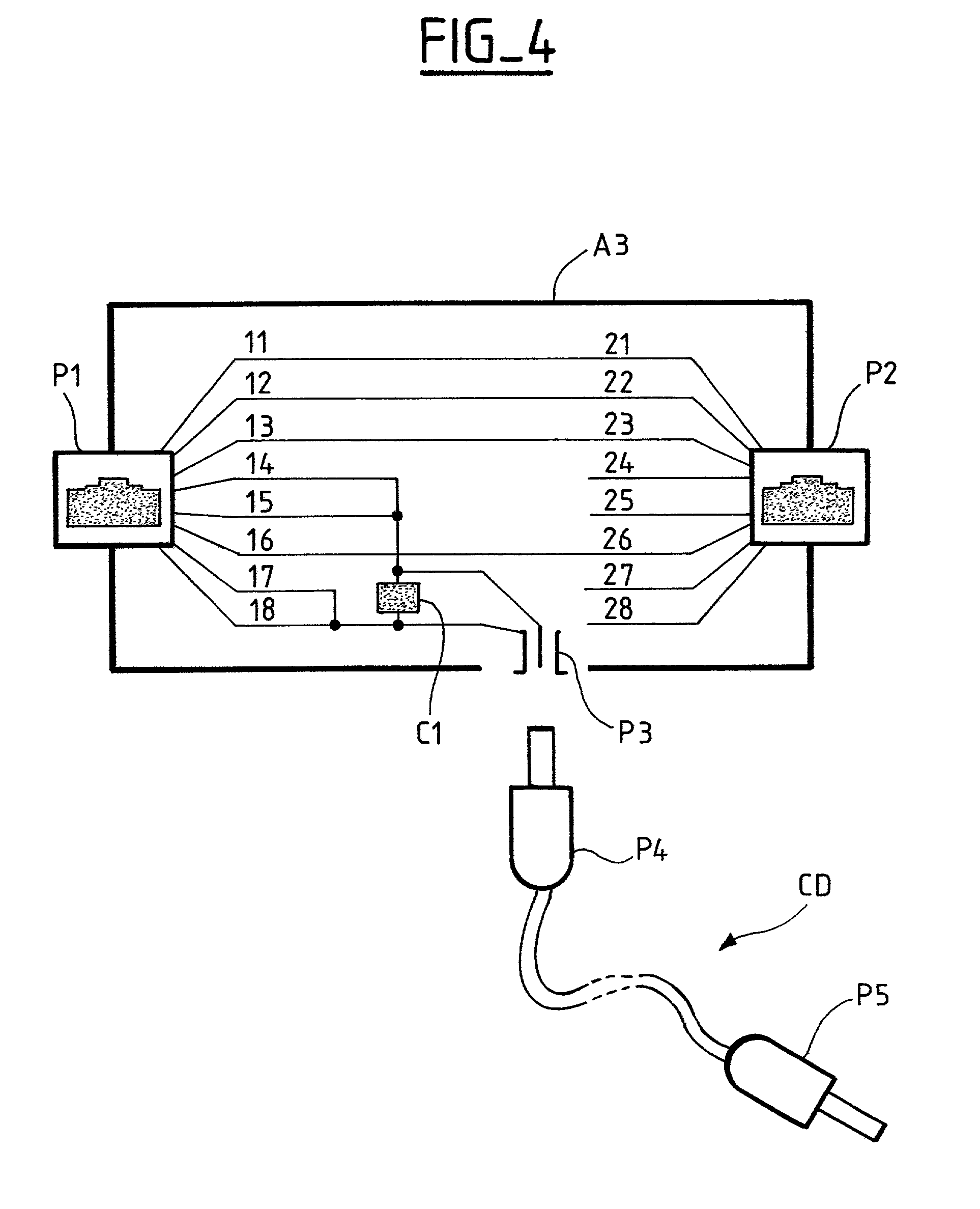
[0029]The above adapter has the advantage that there is no risk if the data input of a terminal that is not adapted to receive a remote power feed is connected to the adapter, because the first connector does not transmit the remote power feed and the second connector cannot be connected to a data input of a terminal.

Problems solved by technology

This solution makes it more difficult to install the local area network:The use of two cables gives rise to problems of congestion, which can also limit the freedom of movement of persons.It creates electrical hazards.
In the case of a telephone, a local power supply from the mains power supply has the further disadvantage that the telephone is unserviceable in the event of a mains power outage, in particular in the event of a fire or natural disaster.
In both cases, providing a remote power feed to a terminal via the computer local area network has the disadvantage that the remote power feed device powers a terminal “blind”.
There is a risk of damaging the electrical circuits of that terminal.
If a relatively high supply voltage, for example 48 volts, is applied to this combination of resistors and capacitors, or to the resistors connected to the center-taps of the transformers, the current flowing in the resistors can destroy them.
It is not practicable to modify existing terminals to adapt them to the interface used by another manufacturer, and it is therefore not possible at present to mix in the same local area network terminals from different manufacturers adapted to receive a remote power feed.

Method used


Image

  • Terminal adapter for connecting a terminal to a computer local area network capable of identifying any of several terminal types
  • Terminal adapter for connecting a terminal to a computer local area network capable of identifying any of several terminal types
  • Terminal adapter for connecting a terminal to a computer local area network capable of identifying any of several terminal types

Examples


first embodiment

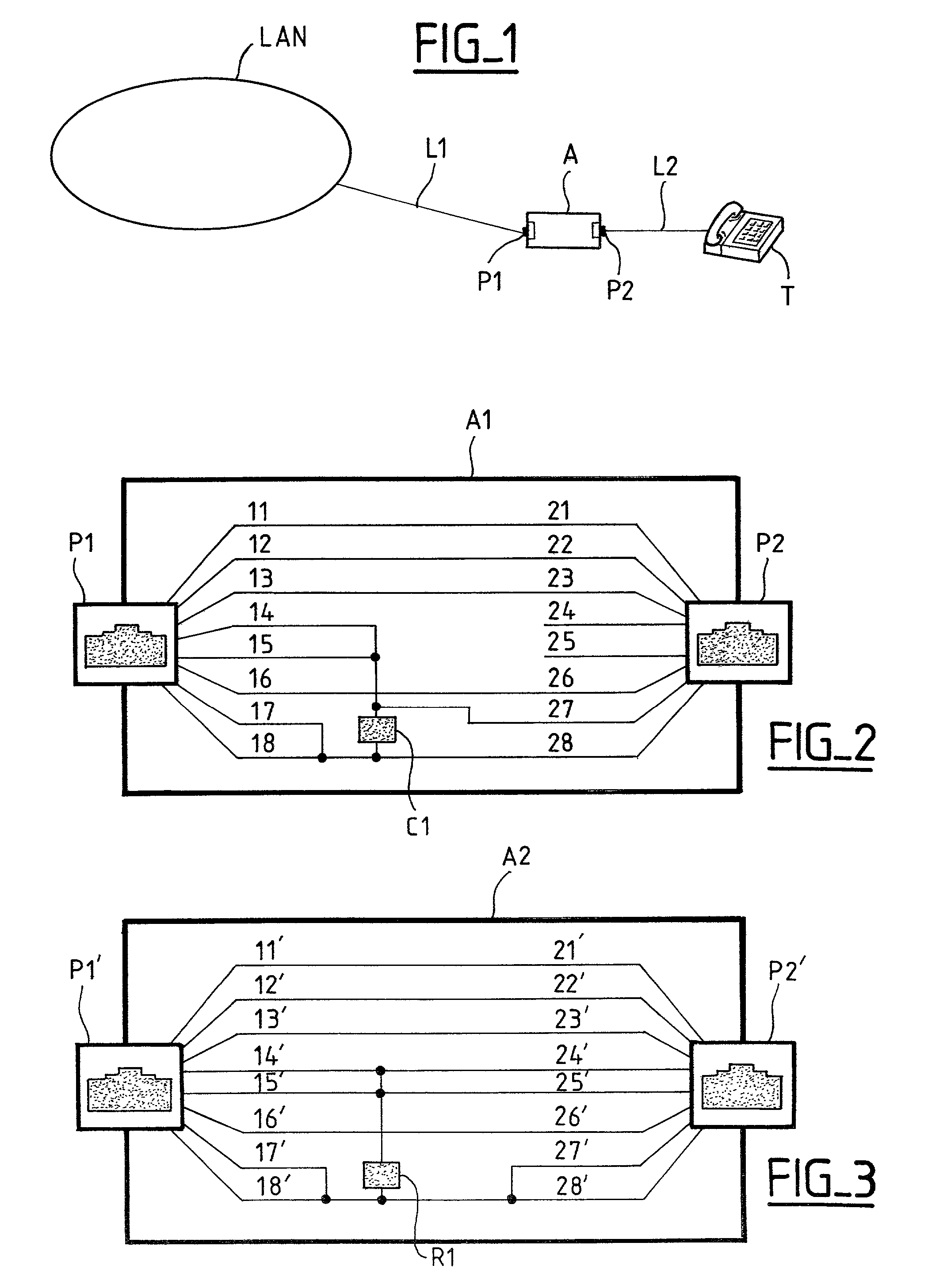
[0036]FIG. 2 shows an adapter according to the invention. The adapter A1 includes a female RJ45 connector P1 at the network end and a female RJ45 connector P2 at the terminal end. Inside the adapter A1, eight conductors 11, . . . , 18 connected to the connector P1 are interconnected with eight conductors 21, 22, . . . , 28 connected to the connector P2. They are interconnected in the following manner:

[0037]11–21: transmission of data.

[0038]12–22: transmission of data.

[0039]13–23: transmission of data.

[0040]14–15–27: one pole of the remote power feed.

[0041]16–26: transmission of data.

[0042]17–18–28: the other pole of the remote power feed.

[0043]The adapter A1 further includes an identifier circuit C1 which has one terminal connected to the conductors 14–15–27 and another terminal connected to the conductors 17–18–28. The identifier circuit C1 is, for example, a capacitor identifying the terminal type “adapted to receive a remote power feed”, according to the specifications of the int...

second embodiment

[0055]FIG. 3 shows an adapter according to the invention. It has a female RJ45 connector P1′ at the network end and a female RJ45 connector P2′ at the terminal end. Inside the adapter A2, eight conductors 11′, . . . , 18′ connected to the connector P1′ are interconnected with eight conductors 21′, . . . , 28′ connected to the connector P2′. They are interconnected in the following manner:

[0056]11′–21′: transmission of data.

[0057]12′–22′: transmission of data.

[0058]13′–23′: transmission of data.

[0059]14′–24′–15′–25′: one pole of the remote power feed.

[0060]16′–26′: transmission of data.

[0061]17′–18′–27′–28′: the other pole of the remote power feed.

[0062]The adapter A2 further includes an identifier circuit R1 which has one terminal connected to the conductors 14′–24′–15′–25′and another terminal connected to the conductors 17′–18′–27′–28′. The identifier circuit R1 is a resistor identifying the terminal type “adapted to receive a remote power feed” for the local area network concerned...


PUM


Abstract

A terminal adapter connects a terminal to a computer local area network capable of identifying any of several terminal types by detecting the presence of a particular identifier electronic circuit specific to one type, even though the terminal does not include any such identifier circuit as standard. The terminal adapter includes first connectors for inserting the adapter between two sections of a connection between the terminal and the network and an identifier circuit specific to one type of terminal that the network is able to detect. The identifier circuit is connected to at least two conductors of a network side section of the connection.

Description

CROSS-REFERENCE TO RELATED APPLICATIONS[0001]This application is based on French Patent Application No. 0100169 filed Jan. 8, 2001, the disclosure of which is hereby incorporated by reference thereto in its entirety, and the priority of which is hereby claimed under 35 U.S.C. §119.BACKGROUND OF THE INVENTION[0002]1. Field of the Invention[0003]The present invention relates to a terminal adapter for connecting a terminal to a computer local area network capable of identifying any of several terminal types. It relates in particular to terminals adapted to be supplied with power locally and to receive a remote power feed via a connection to a computer local area network, for example an Ethernet network.[0004]2. Description of the Prior Art[0005]Conventionally, terminals connected to a computer local area network (for example personal computers, printers, etc.) are supplied with power locally, by the mains power supply. 110 V or 220 V power supply cords independent of the data connectio...

Claims


Application Information

Patent Timeline
Patent Type & Authority Patents(United States)
IPC IPC(8): G06F1/26H04L12/10H04L12/44
CPCH04L12/44H04L12/10
Inventor VERGNAUD, GERARDDORTU, GIOVANNI
Owner ALCATEL LUCENT SAS
Learn More