Embedded RF vertical interconnect for flexible conformal antenna

a technology of flexible conformal antennas and vertical interconnections, which is applied in the association of protected material radiating elements, waveguides, printed circuit non-printed electric components, etc., can solve the problems of microwave circulators and other discrete microwave devices

Inactive Publication Date: 2006-01-31
OL SECURITY LIABILITY CO
View PDF12 Cites 45 Cited by
  • Summary
  • Abstract
  • Description
  • Claims
  • Application Information

AI Technical Summary

Problems solved by technology

Burying microwave circulators and other discrete microwave devices poses a challenge.

Method used


Image

  • Embedded RF vertical interconnect for flexible conformal antenna
  • Embedded RF vertical interconnect for flexible conformal antenna
  • Embedded RF vertical interconnect for flexible conformal antenna

Examples


Embodiment Construction

[0016]In the following detailed description and in the several figures of the drawing, like elements are identified with like reference numerals.

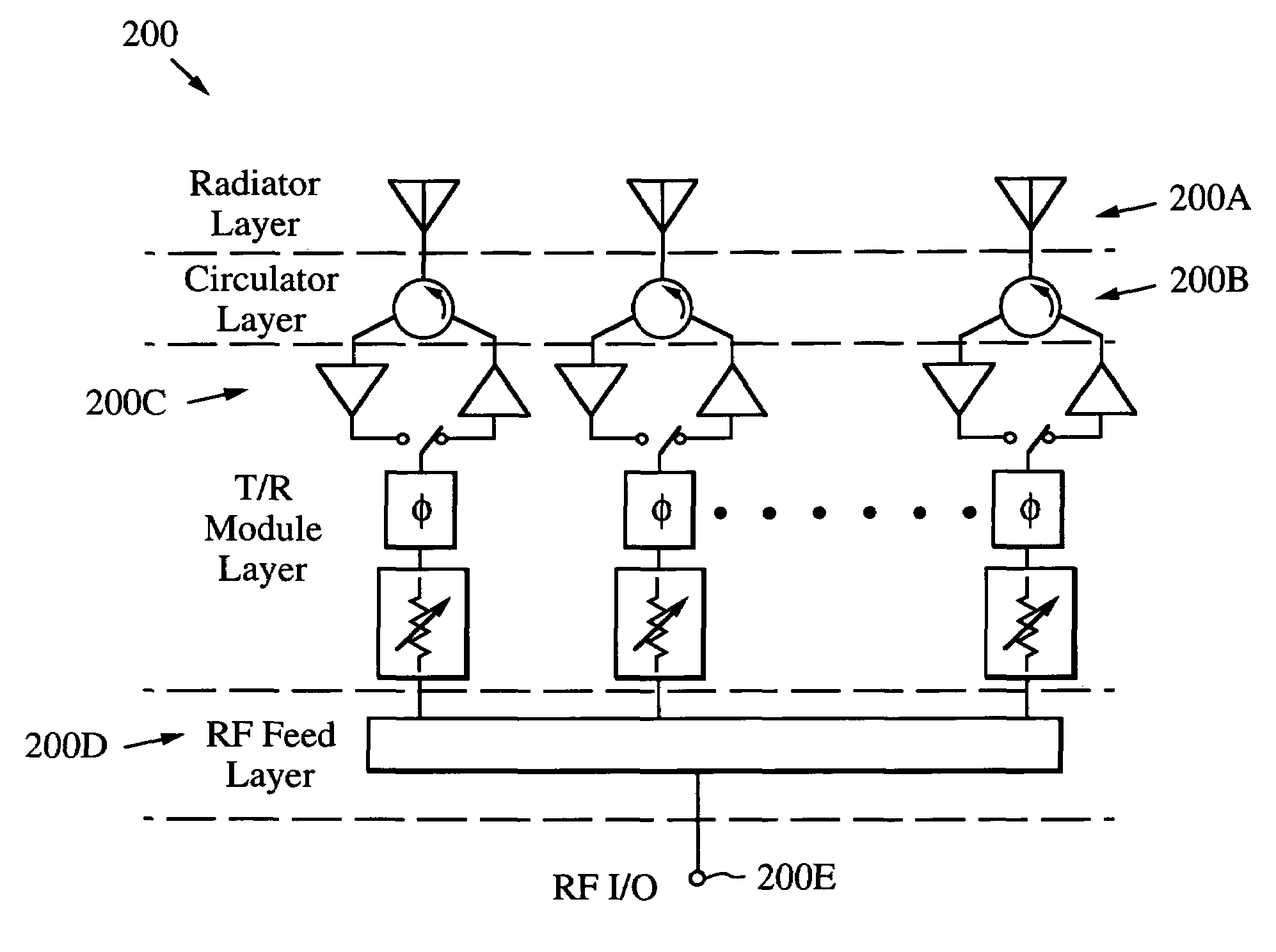
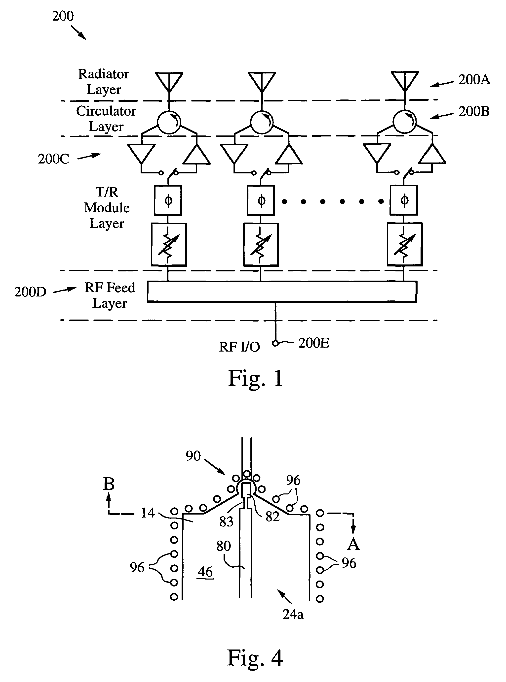
[0017]FIG. 1 is a schematic block diagram of an exemplary embodiment of a active array system 200 which can be implemented in accordance with aspects of this invention. In a general sense, the array includes a radiator layer 200A, a circulator layer 200B, a T / R module layer 200C, and an RF feed layer 200D, with an RF input / output (I / O) port 200E. The T / R module layer includes for each circulator in the layer 200B a phase shifter and an attenuator, as well as a receive amplifier and a transmit amplifier connected to ports of the circulator through a T / R switch. Structures of the array system can be implemented in multiple layers to provide a conformal radiating aperture.

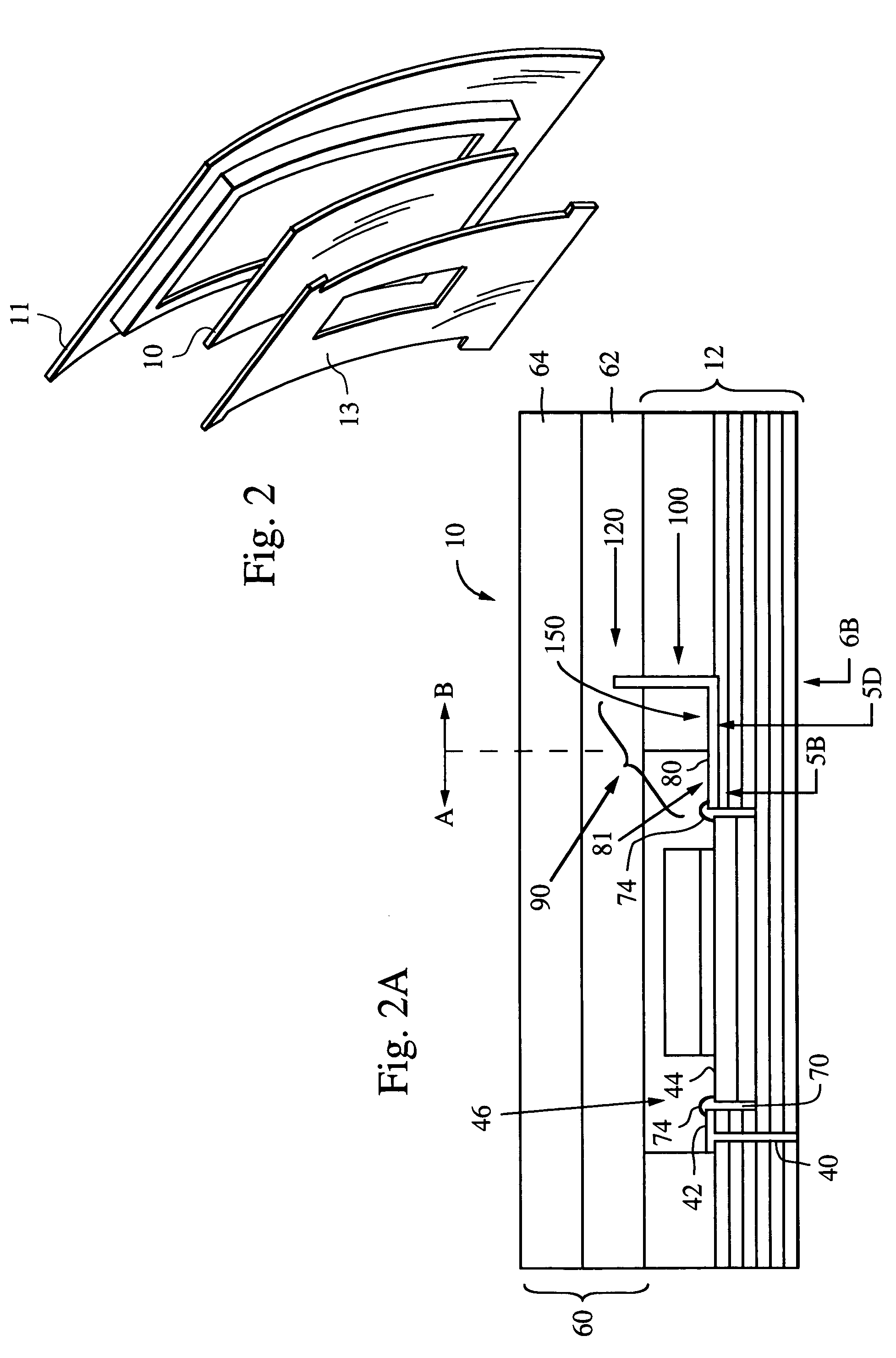
[0018]Turning now to FIG. 2 there is shown an exploded perspective view of a conformal antenna assembly including a multi-layered conformal RF transition structure 10 accordi...


PUM


Abstract

An RF signal transition includes a channelized microstrip transmission structure, and a coplanar wave guide structure in electrical communication with the channelized microstrip transmission structure. A caged troughline transition structure is in electrical communication with the coplanar wave guide structure. A caged coaxial transmission structure is in electrical communication with the troughline transition structure. The signal transition may be embedded in a flexible printed wiring board structure with a circulator for a conformal antenna structure.

Description

BACKGROUND[0001]Typical active array architectures include one or more ferrite circulators for passive duplexing and control of scattering in microwave antennae. These circulators are passive “discrete” microwave devices, which may include, e.g., a microstrip / stripline resonator circuit on a ferrite substrate that is sandwiched between a magnet and magnetic carrier plate.[0002]For a conformal panel architecture, the active devices comprising the T / R modules can be mounted on the back of the panel. The circulators are situated between the radiating apertures and T / R modules. There exists a need to be able to bury these microwave devices, e.g., circulators and other microwave devices, e.g., integrated circuits comprising switches, filters and MEMs, while realizing the vertical transitions to interconnect the devices to the other components within the antenna, e.g., Transmit / Receive modules (T / R modules) and radiators. Burying microwave circulators and other discrete microwave devices ...

Claims


Application Information

Patent Timeline
Patent Type & Authority Patents(United States)
IPC IPC(8): H01Q23/00H01P5/02H01P5/08H01P11/00H01Q1/40H01Q21/00H05K1/00H05K1/02H05K1/16H05K1/18H05K3/46
CPCH01P5/085H01P11/003H01Q1/40H01Q21/0093H01Q23/00H05K1/0222H01L2924/1461H01L2224/45144H01L2924/15311H01L2224/73265H01L2224/48227H05K1/0393H05K1/16H05K1/183H05K3/4614H05K3/4635H05K2201/096H05K2201/09618H05K2201/09809H05K2201/10378H01L2224/16225H01L2224/45014H01L2224/48091H01L2924/00014H01L2924/00H01L2924/206H01P5/08H01P3/08H01Q13/08
Inventor KERNER, STEPHEN R.QUAN, CLIFTONROKOSKY, RAQUEL Z.
Owner OL SECURITY LIABILITY CO
Why Eureka
Try Eureka