Method circuit and system for read error detection in a non-volatile memory array

a non-volatile memory array and error detection technology, applied in static storage, digital storage, instruments, etc., can solve the problems of voltage drift, especially in mlc, corruption of data in memory array,

Active Publication Date: 2006-01-31
SPANSION ISRAEL
View PDF129 Cites 494 Cited by
  • Summary
  • Abstract
  • Description
  • Claims
  • Application Information

AI Technical Summary

Benefits of technology

[0011]The present invention is a method, circuit and system for determining a reference voltage. Some embodiments of the present invention relate to a system, method and circuit for establishing a set of operating reference cells to be used in operating (e.g. reading) cells in a NVM block or array. As part of the present invention, at least a subset of cells of the NVM block or array may be read using each of two or more sets of test reference cells, where each set of test reference cells may generate or otherwise provide reference voltages at least slightly offset from each other set of test reference cells. For each set of test reference cells used to read the at least a subset of the NVM block, a read error rate may be calculated or otherwise determined. A set of test reference cells associated with a relatively low read error rate may be selected as the set of operating reference cells to be used in operating (e.g. reading) other cells, outside the subset of cells, in the NVM block or array. In a further embodiment, the selected set of test reference cells may be used to establish an operating set of reference cells having reference voltages substantially equal to those of the selected test set.

Problems solved by technology

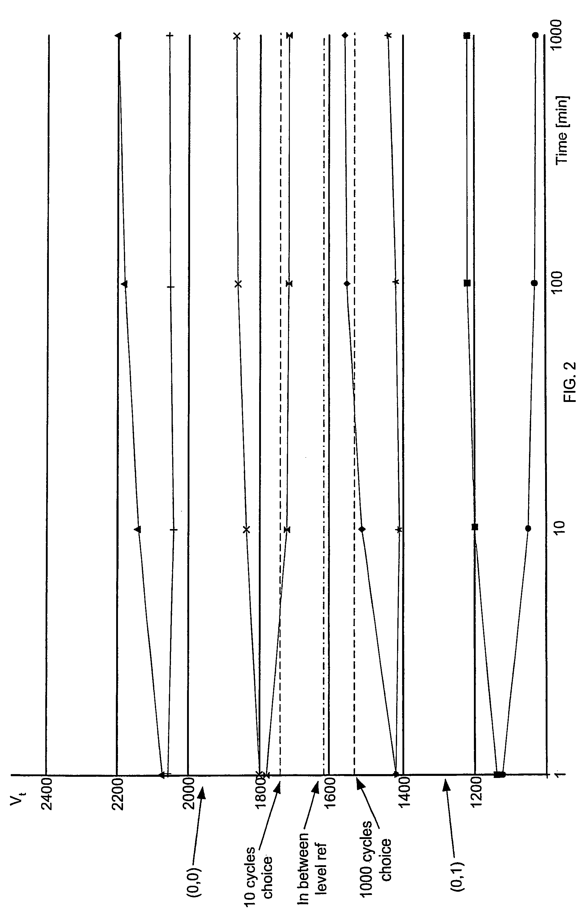
Variation of the threshold voltage of memory cells may lead to false reads of the state and may further result in the corruption of the data in the memory array.
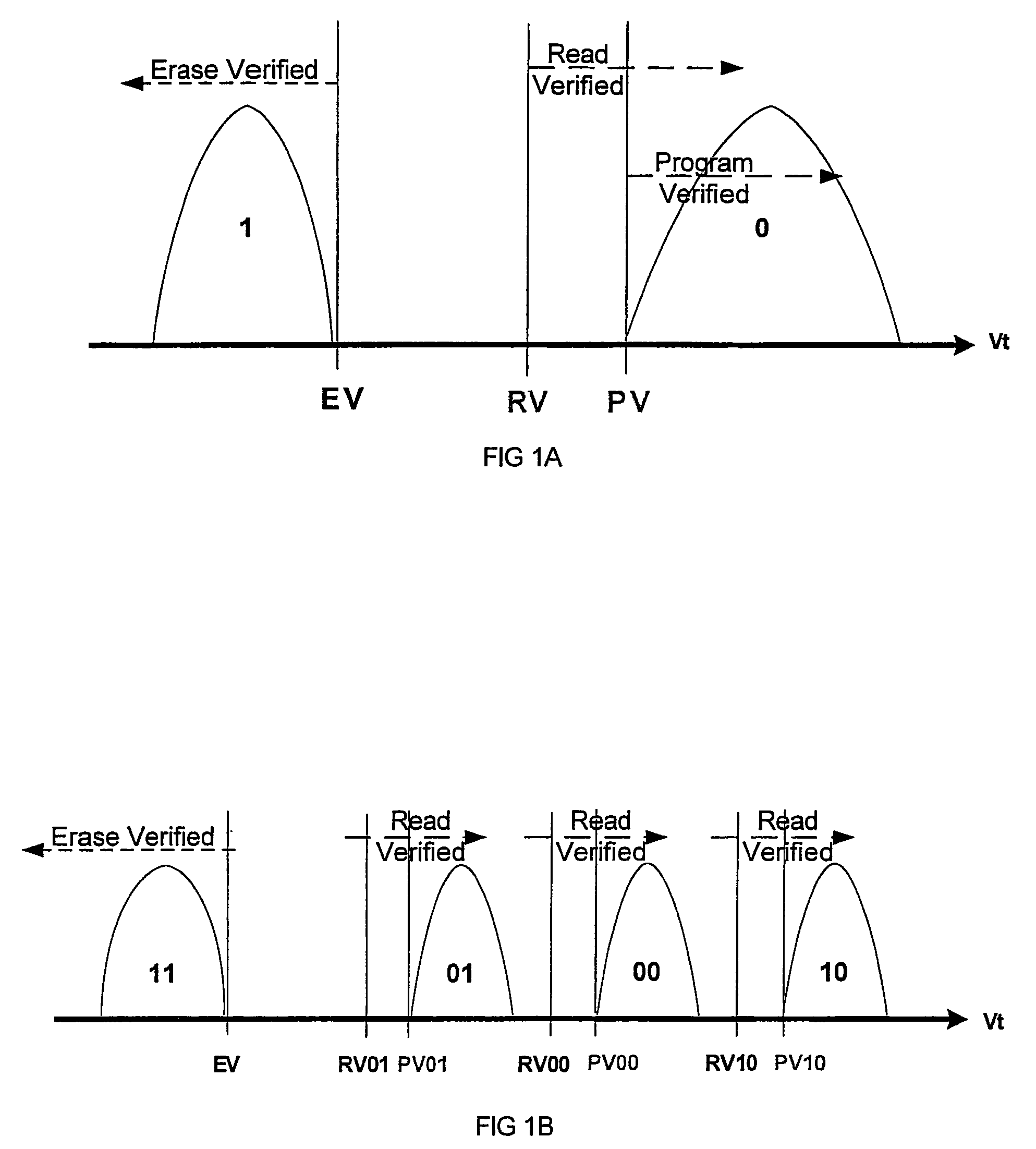
Voltage drift is especially problematic in MLC cells where the Vt regions or sub-ranges associated with each programmed state are relatively smaller than those for a typical binary cell.

Method used


Image

  • Method circuit and system for read error detection in a non-volatile memory array
  • Method circuit and system for read error detection in a non-volatile memory array
  • Method circuit and system for read error detection in a non-volatile memory array

Examples


Embodiment Construction

[0028]In the following detailed description, numerous specific details are set forth in order to provide a thorough understanding of the invention. However, it will be understood by those of ordinary skill in the art that the present invention may be practiced without these specific details. In other instances, well-known methods and procedures have not been described in detail so as not to obscure the present invention.

[0029]The present invention is a method, circuit and system for determining a reference voltage. Some embodiments of the present invention relate to a system, method and circuit for establishing a set of operating reference cells to be used in operating (e.g. reading) cells in a NVM block or array. As part of the present invention, at least a subset of cells of the NVM block or array may be read using each of two or more sets of test reference cells, where each set of test reference cells may generate or otherwise provide reference voltages at least slightly offset f...


PUM


Abstract

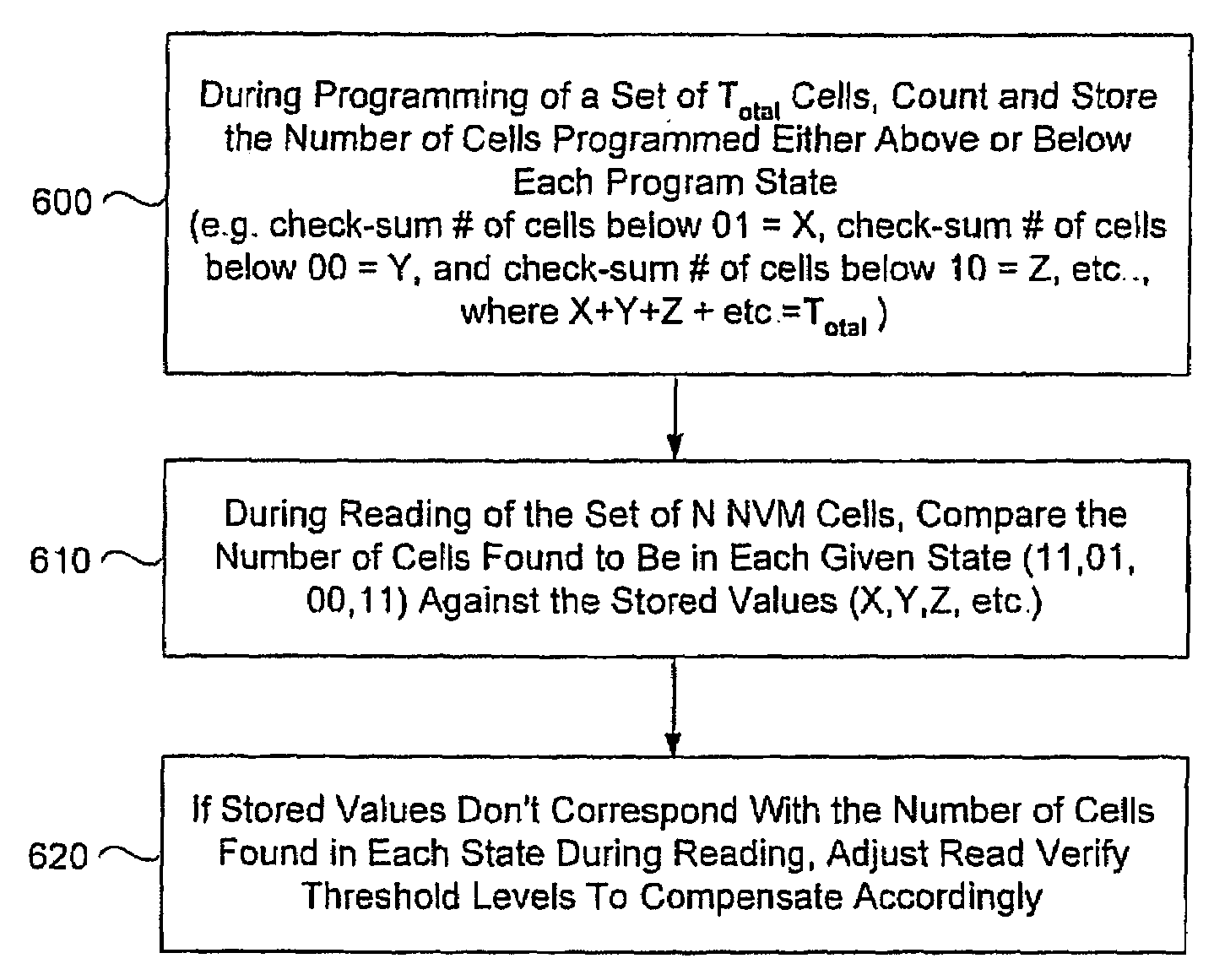
The present invention is a method, circuit and system for determining a reference voltage to be used in reading cells programmed to a given program state. Some embodiments of the present invention relate to a system, method and circuit for establishing a set of operating reference cells to be used in operating (e.g. reading) cells in a NVM block or array. As part of the present invention, at least a subset of cells of the NVM block or array may be read and the number of cells found at a given state associated with the array may be compared to one or more check sum values obtained during programming of the at least a subset of cells. A Read Verify threshold reference voltage associated with the given program state or associated with an adjacent state may be adjusted based on the result of the comparison.

Description

CROSS-REFERENCE TO RELATED APPLICATIONS[0001]The present application is a continuation-in-part of U.S. patent application Ser. No. 10 / 695,448, filed on Oct. 29, 2003 which claims priority from U.S. provisional patent application Ser. No. 60 / 421,785, filed Oct. 29, 2002, which are hereby incorporated by reference in its entirety.FIELD OF THE INVENTION[0002]The present invention generally relates to the field of non-volatile memory (“NVM”) cells. More specifically, the present invention relates to a method and a system for selecting a reference voltage of one or more reference cells in order to read one or more memory cells within a memory cell array.BACKGROUND OF THE INVENTION[0003]NVM cells are generally operated (e.g. programmed, read, and erased) using one or more reference structures or cells. Each of the one or more reference structures or cells may be compared against a memory cell being operated in order to determine a condition or state of the memory cell being operated. As i...

Claims


Application Information

Patent Timeline
Patent Type & Authority Patents(United States)
IPC IPC(8): G11C16/06G06KG11C11/56G11C16/04G11C16/28G11C16/34G11C17/00
CPCG11C11/5642G11C16/04G11C16/28G11C16/3436G11C16/3454G11C16/3459G11C29/00G11C29/026G11C29/028G11C29/42G11C29/52G11C2029/0409G11C2211/5634G11C2211/5644G11C29/24G11C2029/4402
Inventor COHEN, GUY
Owner SPANSION ISRAEL
Why Eureka
Try Eureka