
Gauge and process for adjusting bearings

a bearing and process technology, applied in the direction of mechanical measuring arrangements, bearing unit rigid support, instruments, etc., can solve the problems of affecting the stability of the shaft, and affecting the bearing life of the bearing,

Inactive Publication Date: 2006-02-07
THE TIMKEN CO
View PDF18 Cites 60 Cited by
  • Summary
  • Abstract
  • Description
  • Claims
  • Application Information

AI Technical Summary

Benefits of technology

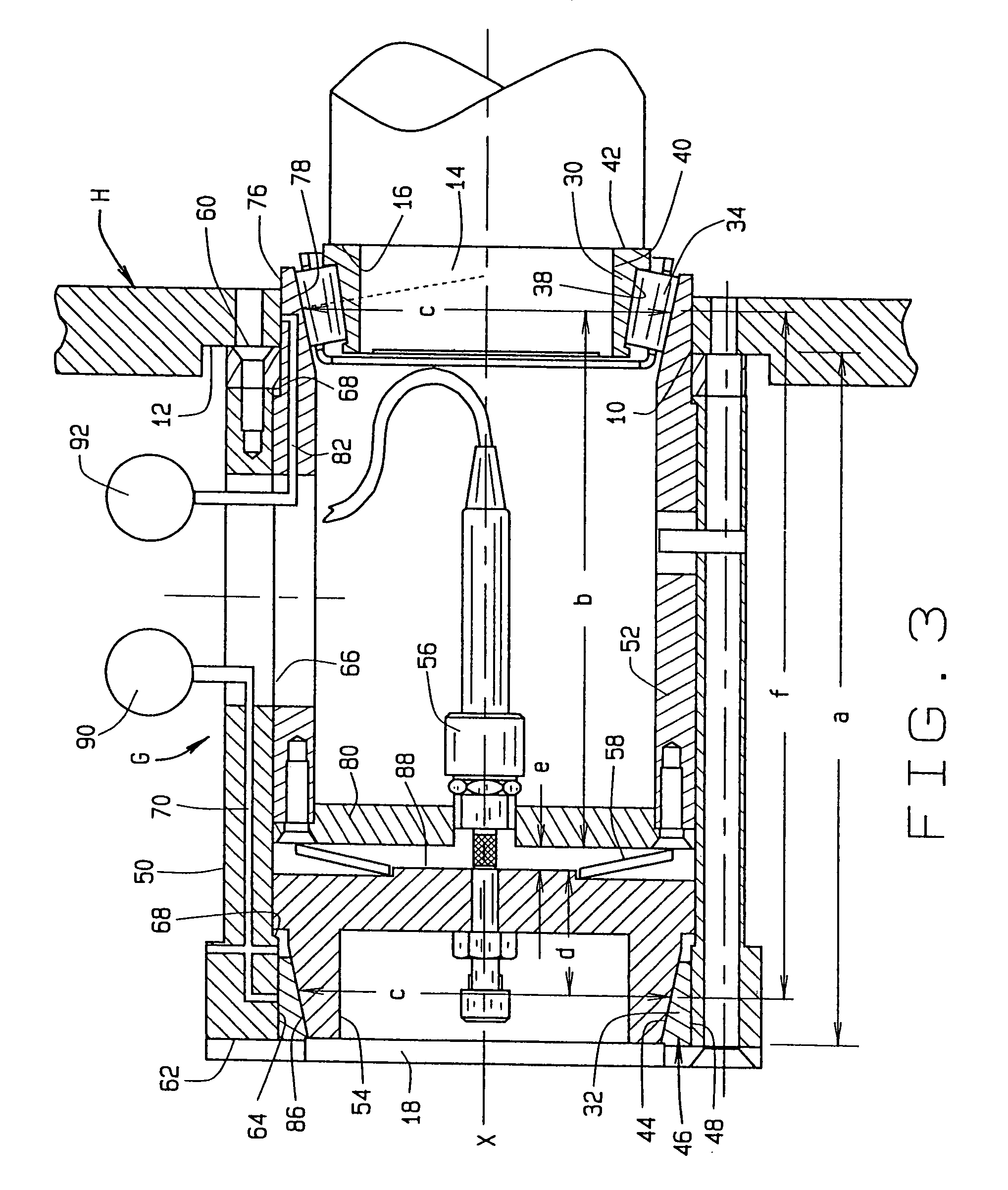
[0007]The present invention resides in a setting gauge which in effect projects a conical envelope out of one of two tapered roller bearings that are mounted in opposition, so that axial measurements may be made between the projected conical envelope and another and identical conical envelope that assumes its normal operating position, all for calculating adjustments necessary to give the bearings the proper setting. The gauge also measures the diameter of a c...

Problems solved by technology

Too much end play concentrates loads in limited regions of the bearings and furthermore creates radial and axial clearances which detract from the stability of the shaft.
Preload insures that the shaft will rotate about a fixed axis and thus provides stability, but too much preload increases friction within the bearings and may lead to early bearing failure.
Perhaps trial and error is the least complex procedure for determining the size of a shim or spacer, but this procedure lacks precision and is more time consuming.
But tolerances in the outer diameter of a cup and in the bore into which it fits can vary the magnitude of the interference fit, and this in turn will produce a variance from the desired setting for the bearings.

Method used


Image

  • Gauge and process for adjusting bearings
  • Gauge and process for adjusting bearings
  • Gauge and process for adjusting bearings

Examples


Embodiment Construction

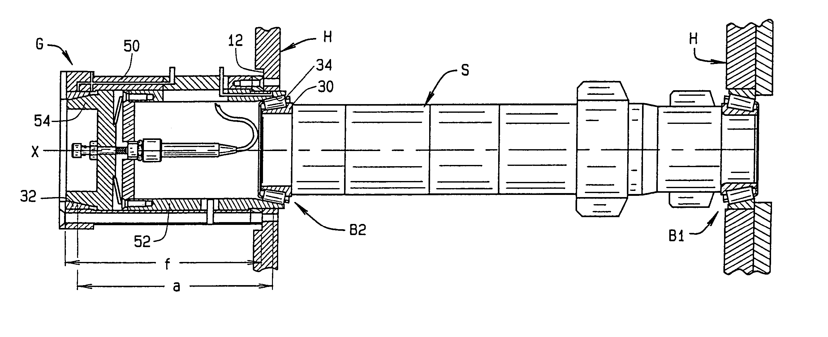
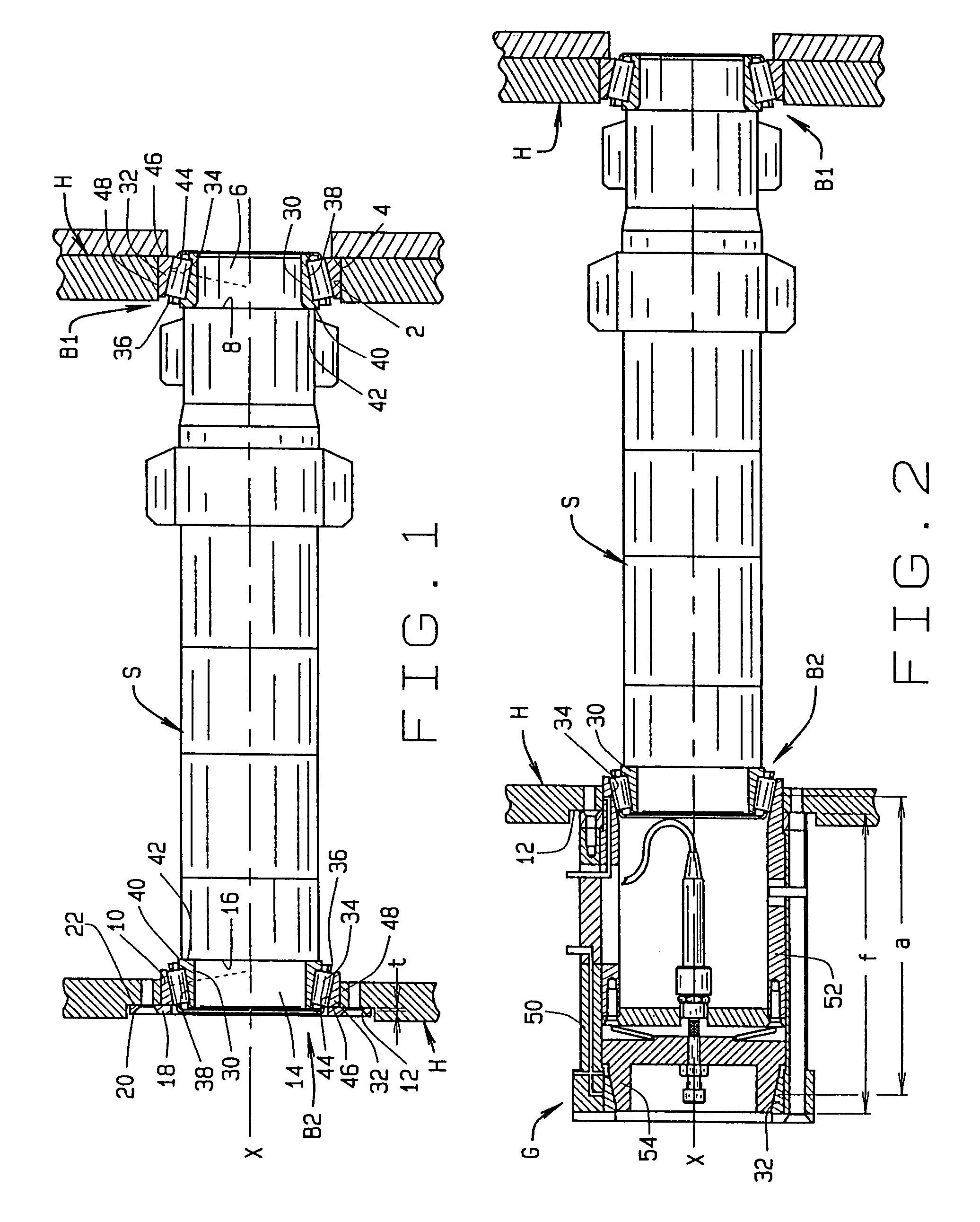
[0011]Referring now to the drawings (FIG. 1), a shaft S rotates in a housing H on two tapered roller bearings B1 and B2 which establish the axis of rotation X for the shaft S. The bearings B1 and B2 transfer radial loads between the shaft S and housing H as well as thrust loads, the bearing B1 taking thrust loads in one axial direction and the bearing B2 in the other. The shaft S constitutes an inner machine component, whereas the housing H constitutes an outer machine component.

[0012]At its one end the housing H contains (FIG. 1) a bore 2 which leads up to a shoulder 4. At the same end the shaft S has a bearing seat 6 which leads up to a shoulder 8 that is presented toward the shoulder 4 in the housing H. The bearing B1 fits into the bore 2 and around the seat 6. At its opposite end the housing H contains a cylindrical through bore 10 that opens out of a reference surface 12 which is recessed and perpendicular to the axis X. The shaft S at this end has a bearing seat 14 which leads...


PUM


Abstract

A setting gauge (G) determines the thickness of a spacer (22) which gives the correct setting for a pair of tapered roller bearings (B1, B2) that are mounted in opposition to accommodate relative rotation between machine components (S, H). The gauge has a base (50) which at one end fits against a surface (12) to which the spacer is to be applied, and at its other end holds one of the races (32) of the bearing (B2) remote from the other race (30) which remains in its operating position. In addition, the gauge has a pair of gauge elements (52, 54), one of which fits against a conical envelope along the remote race and the other of which fits against an identical conical envelope on the race which remains in its operating position, in effect, projecting the conical envelope defined by the in-place race out of the bearing to a remote location so that measurements may be taken from the bearing. The race which is remote during the measurements has a cylindrical surface (48) which is configured to fit another cylindrical surface (10) on one of the machine components (H) with an interference fit, and the gauge also measures the diameters of the two cylindrical surfaces so that the magnitude of the interference fit may be ascertained and its effect on the bearing compensated.

Description

CROSS-REFERENCE TO RELATED APPLICATIONS[0001]This application derives and claims priority from U.S. provisional application 60 / 266,790, filed Feb. 6, 2001, and from International application PCT / US02 / 03979, filed Feb. 6, 2002.TECHNICAL FIELD[0002]This invention relates in general to antifriction bearings and, more particularly, to a gauge and a process for adjusting such bearings.BACKGROUND ART[0003]Wherever shafts rotate in housings one finds bearings of one type or another to support such shafts. Single row tapered roller bearings organized in pairs and mounted in opposition perhaps function best in an installation of this type. These bearings carry heavy radial loads and thrust or axial loads as well. Being mounted in opposition, they can be adjusted against each other to varying conditions of end play or preload. Too much end play concentrates loads in limited regions of the bearings and furthermore creates radial and axial clearances which detract from the stability of the shaf...

Claims


Application Information

Patent Timeline
IPC IPC(8): G01B1/00F16C19/54F16C23/06F16C35/067G01B5/14
CPCF16C19/54F16C23/06G01B5/146F16C35/067F16C2361/61F16C19/547F16C2229/00
Inventor RUSSELL, DANIEL T.RIES, MARK R.
Owner THE TIMKEN CO
Learn More