Ratchet wrench

Inactive Publication Date: 2006-02-07
MARRO RICHARD R
View PDF14 Cites 4 Cited by
  • Summary
  • Abstract
  • Description
  • Claims
  • Application Information

AI Technical Summary

Benefits of technology

[0005]It is an object of the invention to provide improved elements and arrangements thereof in a ratchet wrench f

Problems solved by technology

When working in confined areas, such as automobile engine compartments, it may be difficult, if not impossible, to turn a nut or bolt with a conventional ratchet wrench.
Unfortunately, it is

Method used


Image

  • Ratchet wrench
  • Ratchet wrench
  • Ratchet wrench

Examples


Embodiment Construction

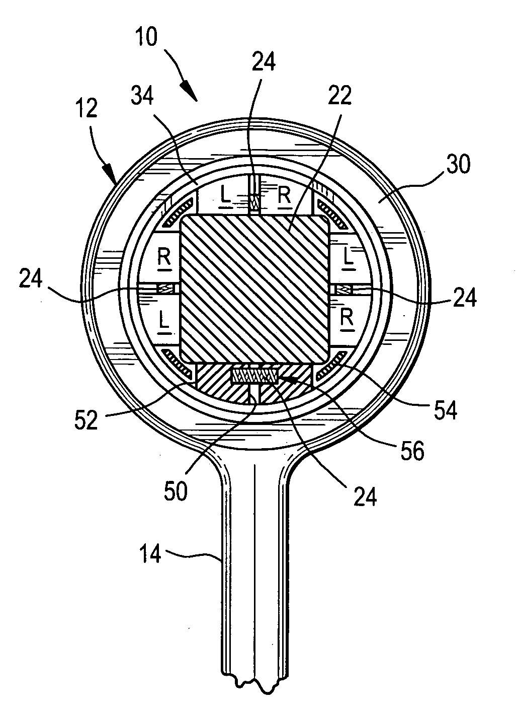
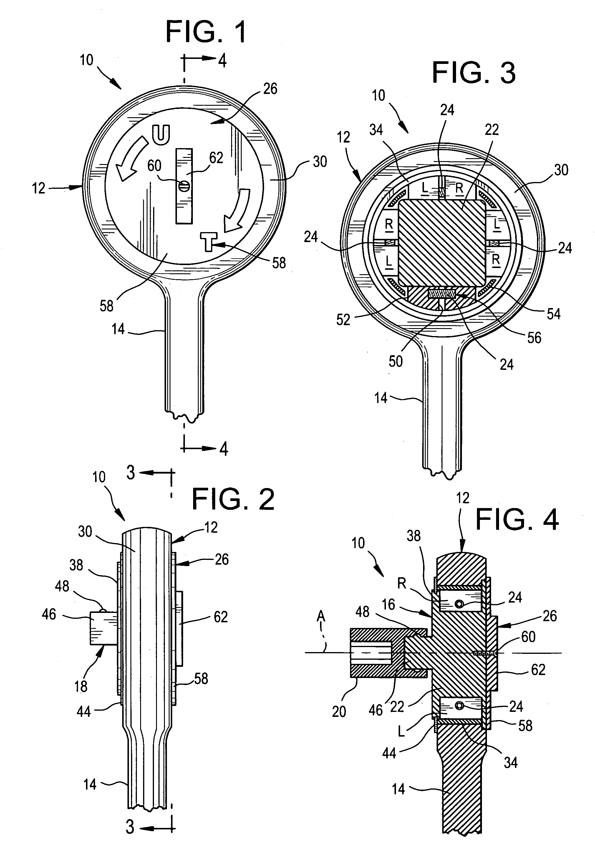
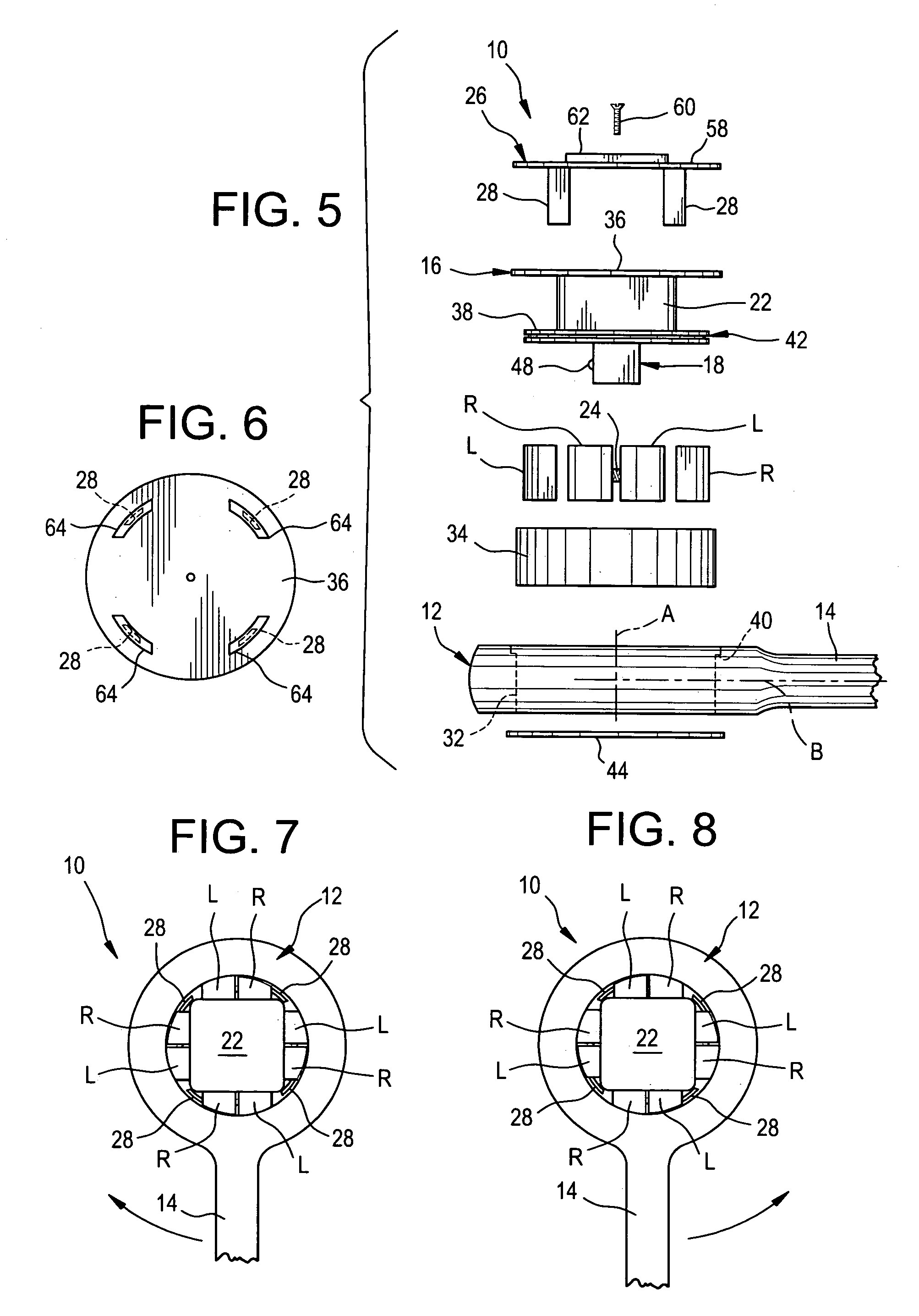
[0018]Referring now to the FIGS., a ratchet wrench in accordance with the present invention is shown at 10. Wrench 10 includes a housing 12 with a handle 14 extending therefrom. A rotor 16 is positioned in housing 12 and has a downwardly extending stem 18 for carrying a socket 20. Rotor 16 also has a crosspiece 22 with a square cross section against each side of which is positioned a pair of wedges L and R. Wedges L and R of each pair are separated by a compressed spring 24 that normally urges such away from one another and into engagement with both housing 12 and crosspiece 22. A selector 26 is rotatably fastened to the top of rotor 16 and has a plurality of arms 28 that extend downwardly between adjacent pairs of wedges L and R. The manual rotation of selector 26 drives arms 28 into either wedges L or wedges R so as to disengage such from housing 12 and permit the ratcheted movement of rotor 16 within housing 12.

[0019]Housing 12 includes a ring 30 having a circular opening 32 whos...


PUM


Abstract

A ratchet wrench including a housing with a handle extending therefrom. A rotor is positioned within an opening in the housing. The rotor includes a crosspiece having a polygonal cross-section and a downwardly extending stem for the selective attachment of a socket. A pair of movable wedges is positioned adjacent each side of the crosspiece. A compressed spring separates the movable wedges of each pair and normally urges the wedges away from one another and into snug engagement with both the housing and the crosspiece. A selector is rotatably fastened to the rotor. The selector includes a disk rotatably fastened to the top of the rotor. A fin extends upwardly from the top of the disk and a plurality of arms extends downwardly from the bottom of the disk with one of the arms being provided for each pair of movable wedges. The arms, by manual rotation of the disk, selectively drive one wedge from each pair of movable wedges from engagement with the housing to permit ratcheting of the wrench.

Description

FIELD OF THE INVENTION[0001]The present invention relates generally to tools and, more particularly, to wrenches with clutched handles.BACKGROUND OF THE INVENTION[0002]Most ratchet wrenches have some play in their ratchet mechanisms. While not always apparent, this play prevents a mechanic from utilizing the full swing of a wrench's handle to turn a nut or bolt. When working in confined areas, such as automobile engine compartments, it may be difficult, if not impossible, to turn a nut or bolt with a conventional ratchet wrench. Unfortunately, it is difficult to determine in advance which areas are too small for a particular ratchet wrench to operate. So, much time and effort can be squandered in the trial and error process to find out.SUMMARY OF THE INVENTION[0003]In light of the problems associated with the known ratchet wrenches, it is a principal object of the invention to provide an improved ratchet wrench that has minimal, i.e., essentially zero, play in its clutch or ratchet ...

Claims


Application Information

Patent Timeline
IPC IPC(8): B25B13/00
CPCB25B13/465B25B13/462
Inventor MARRO, RICHARD R.
Owner MARRO RICHARD R
Why Eureka
Try Eureka