Cap device for mixing different kinds of materials separately contained therein and in bottle

a technology of a cap and a bottle, which is applied in the direction of cooling fluid circulation, lighting and heating apparatus, domestic cooling apparatus, etc., can solve the problems of inconvenient use, unfavorable use of natural resources, and difficulty for most users to add a precise amount of additive from the separate container, so as to facilitate the preparation of the mixture

Inactive Publication Date: 2006-02-07
CHO YOUNG KOOK
View PDF8 Cites 47 Cited by
  • Summary
  • Abstract
  • Description
  • Claims
  • Application Information

AI Technical Summary

Benefits of technology

[0010]Accordingly, the present invention has been made keeping in mind the above problems occurring in the prior art, and an object of the present invention is to provide a cap device for bottles, which is capable of mixing an additive contained therein with a bottled material to prepare a mixture in accordance with a simple rotating action of the cap device relative to a bottle, performed by a user, thereby allowing the user to easily prepare the mixture just before taking or using the mixture.
[0011]Another object of the present invention is to provide a cap device for bottles, in which a valve means is stably placed at a desired position in a neck of the bottle, without being undesirably displaced.
[0012]A further object of the present invention is to provide a cap device for bottles, which allows the additive and the material to be completely and separately stored in the cap device and the bottle, respectively, such that the additive is not undesirably added to the bottled material.
[0014]The cap device further comprises: a sealing means provided at a junction between the valve member and the lower end of the funnel part of the cap body, thus accomplishing a sealing effect at the junction.

Problems solved by technology

Therefore, it is necessary for manufacturers of the additives and the bottled materials to separately contain such additives and materials in separate containers and bottles prior to marketing them, thus undesirably wasting natural resources due to the production of the separate containers and capped bottles.
In addition, the adding of the additive from the separate container to the bottled material to mix them after removing the cap from the bottle is inconvenient to the user in that the user is forced to separately purchase and handle the additive container and the bottle.
Furthermore, it is extremely difficult for most users to add a precise amount of the additive from the separate container to the material contained in the bottle, and so that the user roughly measures the amount of the additive to be added to the bottled material.
Therefore, in the case of mixing of an additive with a bottled drink to produce a mixed beverage, the rough measurement of the amount of the additive may result in change in taste and quality of the mixed beverage.
In the case of mixing of an additive with a bottled liquid medicine or a bottled liquid chemical to produce a mixed medicine or a mixed chemical, the rough measurement of the amount of the additive may result in incomplete dissolution of effective ingredients of the additive in the medicine or the chemical and a failure of accomplishment of desired medical or chemical effects of the mixed medicine or the mixed chemical.
However, the mixtures which are prepared by the manufacturers and marketed in the bottled state are problematic in that the effects of ingredients of the bottled mixtures may be gradually degraded with progressive passage of time, in addition to change in colors of the mixtures.
Furthermore, the bottled mixtures may generate floating matters and deposit therein with gradual passage of time.
However, since the outside ends of the above radial ribs are formed as free ends, the radial ribs may be easily bent or deformed.
Therefore, the valve means may be easily displaced in the neck of the bottle.

Method used


Image

  • Cap device for mixing different kinds of materials separately contained therein and in bottle
  • Cap device for mixing different kinds of materials separately contained therein and in bottle
  • Cap device for mixing different kinds of materials separately contained therein and in bottle

Examples


first embodiment

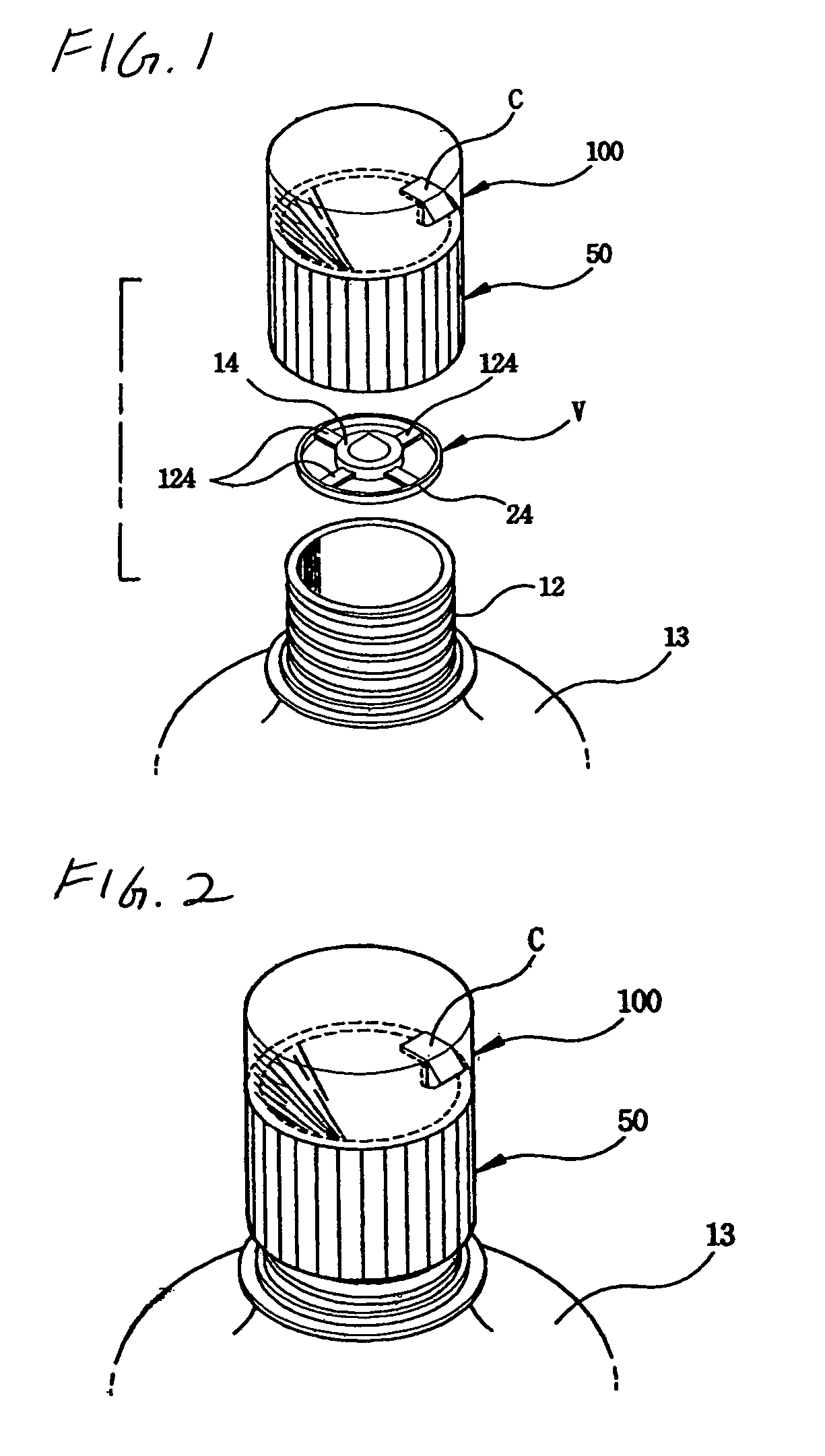
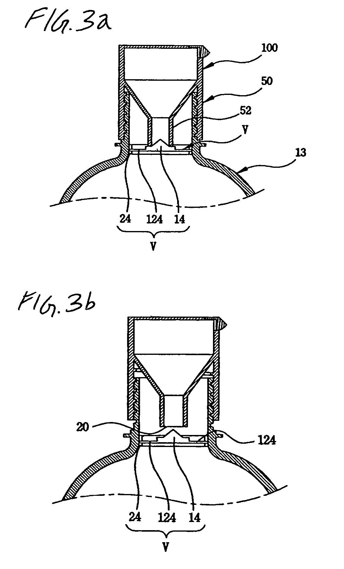
[0023]FIGS. 1 through 3b are views of a cap device for bottles according to the present invention. As shown in the drawings, the cap device according to the present invention comprises a cap body 50, and a cap cover 100 assembled with the cap body 50 to define a cavity therein for containing an additive. The cap device also has a valve means to allow the cavity defined by the cap body 50 and the cap cover 100 to selectively communicate with an interior of a bottle 13.

[0024]In a detailed description, the cap body 50 is tightened to an externally threaded mouth 12 of the bottle 13, with a funnel part 52 integrally formed in the cap body 50 to discharge the additive into the bottle 13 through a lower end thereof.

[0025]The cap cover 100 is assembled with the cap body 50 to cover an open upper end of the cap body 50 while defining the cavity inside both the cap body 50 and the cap cover 100 to contain the additive in the cavity.

[0026]In the first embodiment, the valve means comprises a v...

second embodiment

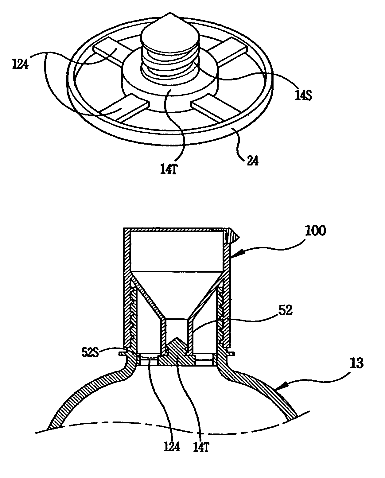
[0029]FIGS. 4a and 4b are views of an alternative valve means of the cap device, according to the present invention. As shown in the drawings, a sealing means is provided at a junction between the valve member “V” and the lower end of the funnel part 52 of the cap body 50, thus accomplishing an airtight or watertight sealing effect at the junction. The sealing means is provided at the conical valve part 14 of the valve member “V”. That is, the sealing means comprises a plugging shank 14S of a conical valve body extending upward from a valve holder 14T of the conical valve part 14. An external thread is formed around the plugging shank 14S, such that the external thread of the plugging shank 14S has the same pitch as an internal thread of the lower end of the funnel part 52 of the cap body 50. In order to engage with the external thread of the plugging shank 14S, the lower end of the funnel part 52 is provided with an engaging part 52S on an internal surface thereof. Due to the seali...


PUM


Abstract

A cap device for bottles, in which a valve means is stably placed at a desired position in a neck of the bottle, without being undesirably displaced, and which allows an additive and a material to be completely separately stored in the cap device and the bottle, respectively, such that the additive is not undesirably added to the bottled material. The cap device has a cap body tightened to an externally threaded mouth of a bottle, with a funnel part integrally formed in the cap body to discharge an additive from the cap body into the bottle through a lower end thereof. A cap cover is assembled with the cap body to cover an open upper end of the cap body while defining a cavity inside both the cap body and the cap cover to contain the additive in the cavity. The cap device also has a valve means for opening or closing the lower end of the funnel part of the cap body in accordance with a rotating action of the cap body relative to the externally threaded mouth of the bottle. The valve means comprises a valve member having a conical valve part to be brought into close contact with or spaced apart from the lower end of the funnel part of the cap body, thus closing or opening the lower end of the funnel part. A plurality of radial ribs extend outward from an external surface of the conical valve part in radial directions. A ring is integrated with outside ends of the radial ribs so as to be supported on an inner surface of a neck of the bottle.

Description

BACKGROUND OF THE INVENTION[0001]1. Field of the Invention[0002]The present invention relates, in general, to caps for bottles which contain a variety of materials, such as drinks, liquid medicines or liquid chemicals, therein and, more particularly, to a cap device for such bottles, which is capable of mixing an additive contained therein with a material contained in a bottle to prepare a mixture in accordance with a simple rotating action of the cap device relative to the bottle, performed by a user, thus allowing the user to easily prepare the mixture just before taking or using the mixture.[0003]2. Description of the Related Art[0004]In the prior art, most conventional disposable bottles circulated and sold in markets each contain therein only a single kind of material, such as a drink, a liquid medicine or a liquid chemical, and are closed by caps at mouths thereof. When a user wants to add an additive to the material contained in such a capped bottle so as to prepare a mixture...

Claims


Application Information

Patent Timeline
Patent Type & Authority Patents(United States)
IPC IPC(8): B65D25/08B65D51/28F25D5/02F25D31/00
CPCB65D51/2864F25D5/02Y10S215/08F25D2331/803F25D31/007B65D51/28
Inventor CHO, YOUNG KOOK
Owner CHO YOUNG KOOK
Why Eureka
Try Eureka