Magnetic tape cartridge

Inactive Publication Date: 2006-02-07
FUJIFILM CORP +1
View PDF15 Cites 0 Cited by
  • Summary
  • Abstract
  • Description
  • Claims
  • Application Information

AI Technical Summary

Benefits of technology

[0018]The ribs are provided such that one of the upper case and the lower case is provided with a first rib; and the other of the upper case and the lower case is provided with two ribs that sandwich the first rib therebetween. However, a greater number of ribs may be provided.
[0019]The ribs are preferably provided such that lateral surfaces of adjacent ribs are welded to each other and/or such that portions of the ribs that extend beyond the abutment surfaces are welded to the side walls of the case into which the ribs extend. By adopting this construction, the strength can be further improved.
[0020]According to the magnetic tape cartridge of the present invention, the abutment surfaces of the upper and lower cases are welded to each other, and vertically extending ribs that extend beyond the abutment surfaces are alternately provided on the inner surfaces of the side walls of each case, in the vicinity of the opening. Therefore, the portions of the ribs that extend beyond the abutment surfaces incr

Problems solved by technology

Accordingly, the structural integrity of the cartridge case at this portion is low.
However, simply welding

Method used


Image

  • Magnetic tape cartridge
  • Magnetic tape cartridge
  • Magnetic tape cartridge

Examples


Example

[0033]Hereinafter, the present invention will be described in detail with reference to the embodiment shown in the attached figures.

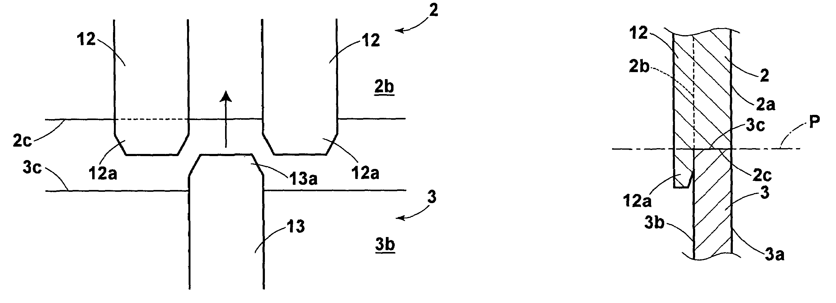
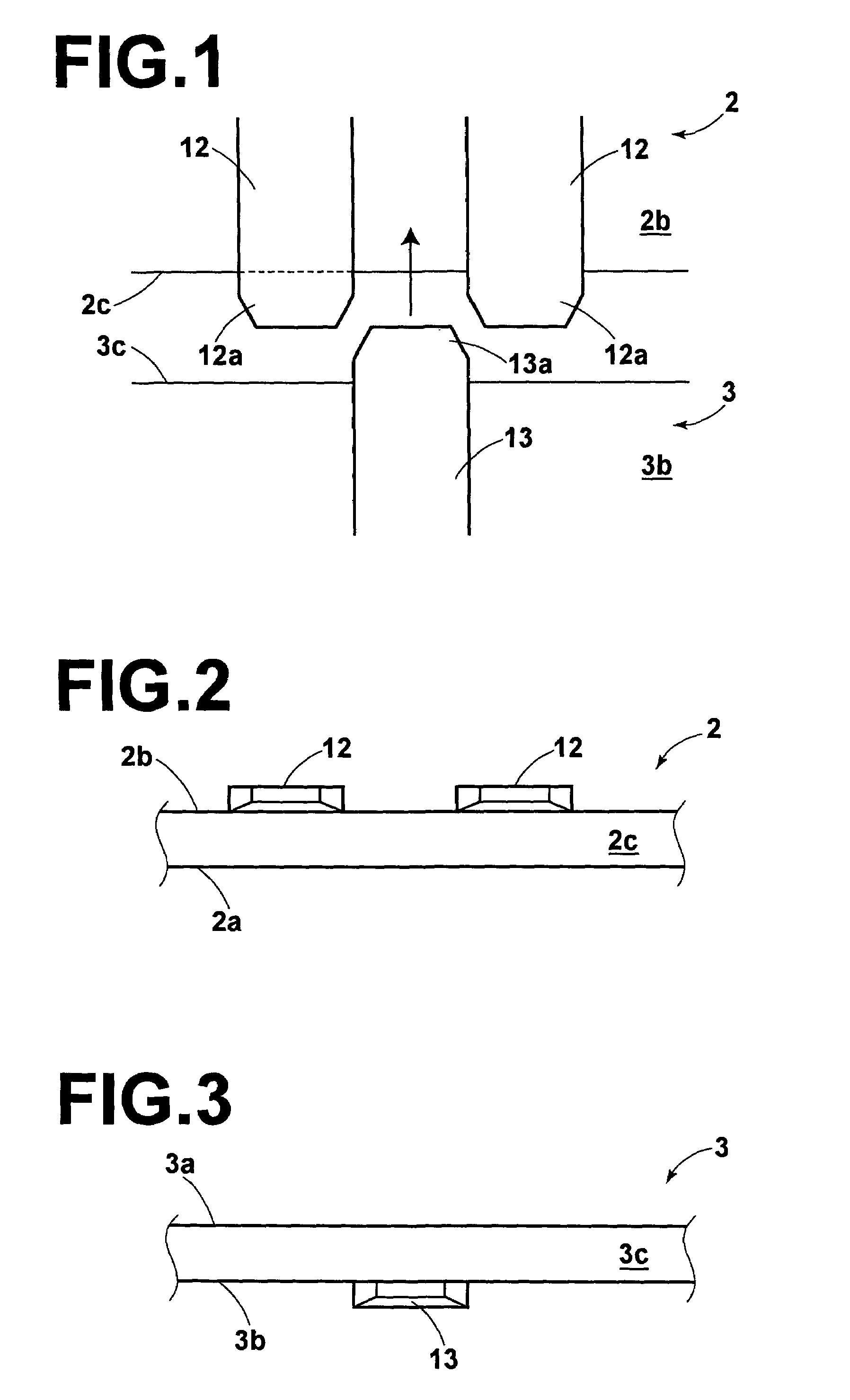
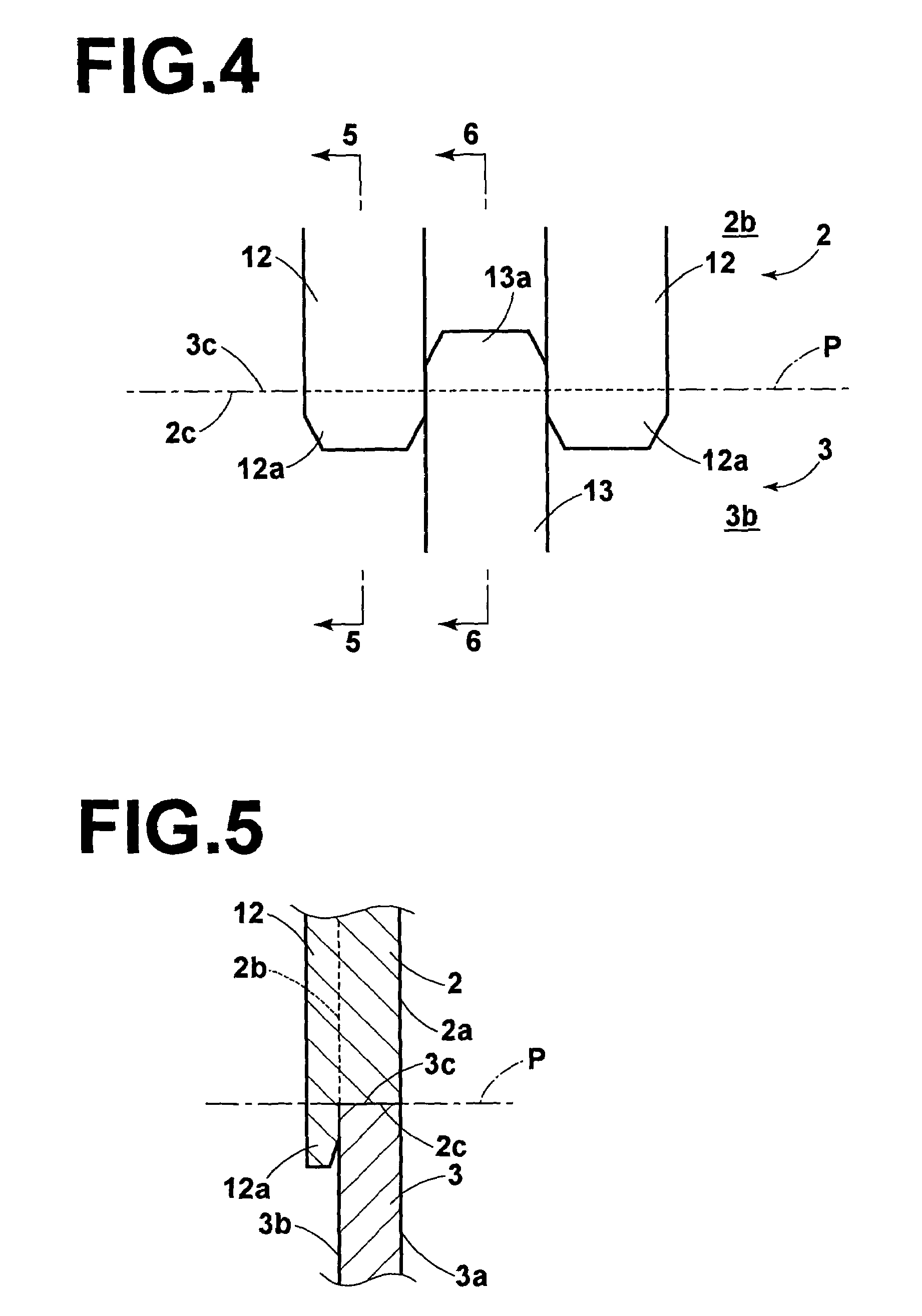
[0034]FIG. 1 is a front view showing the structure of inner surfaces of side walls in the vicinity of an opening of an upper case and a lower case of a magnetic tape cartridge according to an embodiment of the present invention, prior to welding. FIG. 2 is a bottom view of the side wall of the upper case. FIG. 3 is a plan view of the side wall of the lower case.

[0035]A side wall of an upper case 2 comprises: a substantially vertical outer surface 2a; a substantially vertical inner surface 2b; and a horizontal bottom surface 2c, which acts as an abutment surface for abutting a side wall of a lower case 3. Two ribs 12 and 12, each having a distal end portion 12a that extends downwardly beyond the bottom surface 2c, are integrally provided on the inner surface 2b in the vicinity of an opening, with a predetermined interval therebetween.

[0036]The side wall ...


PUM


Abstract

A magnetic tape cartridge is constructed by rotatably housing a reel having magnetic tape wound therearound within a cartridge case. The cartridge case is constructed by an upper case and a lower case. The cartridge case has a tape extraction opening in a side wall thereof. The upper case and the lower case are fixed by welding at an abutment surface P, where the upper case and the lower case abut each other. In addition, vertically extending ribs that alternately extend up and down beyond the abutment surface P are provided on the inner surfaces of the side walls of the upper case and the lower case in the vicinity of the opening. By this construction, the strength of the cartridge case in the vicinity of the opening is improved, thereby preventing damage thereto even when the magnetic tape cartridge is dropped or the like.

Description

BACKGROUND OF THE INVENTION[0001]1. Field of the Invention[0002]The present invention relates to a magnetic tape cartridge comprising a single reel having magnetic tape wrapped therearound, rotatably housed within a cartridge case. Particularly, the present invention relates to the structure of the cartridge case.[0003]2. Description of the Related Art[0004]There are known magnetic tape cartridges of the type wherein a single reel having magnetic tape wrapped therearound is rotatably housed within a cartridge case, as disclosed in, for example, Japanese Unexamined Patent Publication Nos.11 (1999)-306722, 2001-148179, and 2001-266533. These magnetic tape cartridges are conventionally employed as recording media in external memory devices for computers and the like.[0005]FIG. 10 is a perspective view that shows the entirety of a magnetic tape cartridge 1 of this type, in a state in which a slide door 11 is open. A tape extraction opening 10 is formed on a side wall of a cartridge case...

Claims


Application Information

Patent Timeline
IPC IPC(8): G11B23/107
CPCG11B23/107
Inventor FUJII, AKIHIKOTSUYUKI, SEIJI
Owner FUJIFILM CORP
Why Eureka
Try Eureka