Coated rolling element bearing cages

a technology of rolling element bearings and cages, which is applied in the direction of bearings, shafts and bearings, rotary machine parts, etc., can solve the problems of debris still present in the system, ingested into the system, and debris trapped in the silver coating is especially harmful

Active Publication Date: 2006-02-07
THE TIMKEN CO
View PDF13 Cites 47 Cited by
  • Summary
  • Abstract
  • Description
  • Claims
  • Application Information

AI Technical Summary

Benefits of technology

[0007]In accordance with the invention, briefly stated, a coating is applied to the cages, rather than the lands, bearing elements, or raceways. The coating of the present invention performs the desirable functions of the silver, without the ability ...

Problems solved by technology

A prevalent problem with this approach is that debris still present from the manufacturing process of the system, ingested into the system during operation, or evolved in the system through normal operation becomes trapped in the silver coating.
Debris trapped in the silver coating is especially harmful when it is located on the regions of the cage th...

Method used


Image

  • Coated rolling element bearing cages
  • Coated rolling element bearing cages

Examples


Embodiment Construction

[0020]The following detailed description illustrates the invention by way of example and not by way of limitation. This description will clearly enable one skilled in the art to make and use the invention, and describes what we presently believe is the best mode of carrying out the invention. Additionally, it is to be understood that the invention is not limited in its application to the details of construction and the arrangements of components set forth in the following description or illustrated in the drawings. The invention is capable of other embodiments and of being practiced or being carried out in various ways. Also, it is to be understood that the phraseology and terminology used herein is for the purpose of description and should not be regarded as limiting.

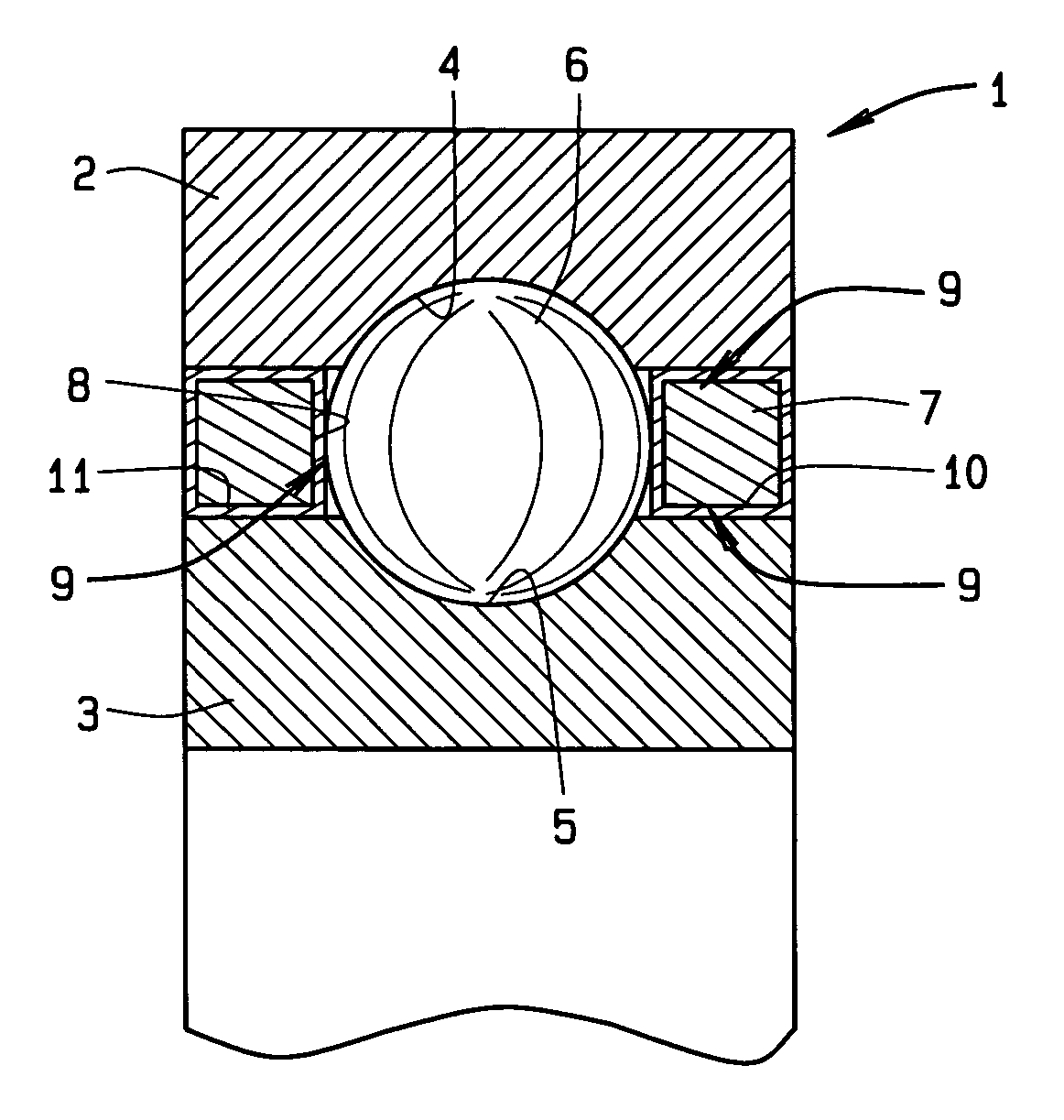
[0021]FIG. 1 shows an axial cross-section through a deep groove ball bearing 1. The ball bearing 1 has an outer ring 2 and an inner ring 3, each of which are provided with a respective raceway 4, 5. The raceways 4, 5 a...


PUM


Abstract

A rolling element bearing comprises an inner ring (3) and an outer ring (2) each provided with a raceway (4, 5), said rings having land regions (10, 11) on opposite sides of their raceways, and a series of rolling elements (6) which are in rolling contact with the raceways and which are mutually spaced by a cage (7), said cage (7) engaging the land regions (10, 11) of said ring, said cage (7) being coated with a wear and friction reducing coating over its full surface.

Description

CROSS-REFERENCE TO RELATED APPLICATIONS[0001]This application claims priority to provisional application Ser. No. 60 / 454,831, filed Mar. 14, 2003, and which is incorporated herein by reference.STATEMENT REGARDING FEDERALLY SPONSORED RESEARCH OR DEVELOPMENT[0002]Not Applicable.BACKGROUND OF THE INVENTION[0003]This invention is related to rolling element bearings, and in particular, to a coating for the cage of such a bearing.[0004]Rolling element bearings comprise an inner ring and an outer ring each provided with a raceway. At least one of the rings has land regions on opposite sides of the respective raceway. A series of rolling elements which are in rolling contact with the raceways are maintained in a spaced-apart relationship by a cage. The cage engages the land regions of the ring.[0005]It is a known practice to apply solid lubricant coatings such as silver to the cages in rolling element bearings for some applications. The silver coatings on the cages have two functions: (1) t...

Claims


Application Information

Patent Timeline
IPC IPC(8): F16C19/06F16C33/44F16C33/66
CPCF16C33/445F16C33/6696F16N2210/14F16C19/06F16C33/3806F16C2240/64
Inventor DOLL, GARY L.EVANS, RYAN D.RIBAUDO, CARL R.
Owner THE TIMKEN CO
Why Eureka
Try Eureka