Leading edge diffusion cooling of a turbine airfoil for a gas turbine engine

a technology of diffusion cooling and turbine airfoil, which is applied in the direction of machines/engines, rotary propellers, propulsive elements of rotary type, etc., can solve the problems of stress, loss of downstream film cooling effectiveness, and dilution of coolant, so as to improve the cooling of the leading edge

Inactive Publication Date: 2006-02-07
FLORIDA TURBINE TECH
View PDF2 Cites 49 Cited by
  • Summary
  • Abstract
  • Description
  • Claims
  • Application Information

AI Technical Summary

Benefits of technology

[0009]An object of this invention is to provide for a turbine of a gas turbine engine improved cooling of the leading edge.

Problems solved by technology

Some of the coolant is subsequently injected directly into the mainstream causing turbulence, coolant dilution and loss of downstream film cooling effectiveness.
Furthermore, film cooling hole breakout on the airfoil surface may induce stress problems.

Method used


Image

  • Leading edge diffusion cooling of a turbine airfoil for a gas turbine engine
  • Leading edge diffusion cooling of a turbine airfoil for a gas turbine engine
  • Leading edge diffusion cooling of a turbine airfoil for a gas turbine engine

Examples


Embodiment Construction

[0018]While this invention is being described showing a particular configured turbine blade as being the preferred embodiment, as one skilled in this art will appreciate, the principals of this invention can be applied to any other turbine blade that requires internal cooling and could be applied to vanes as well.

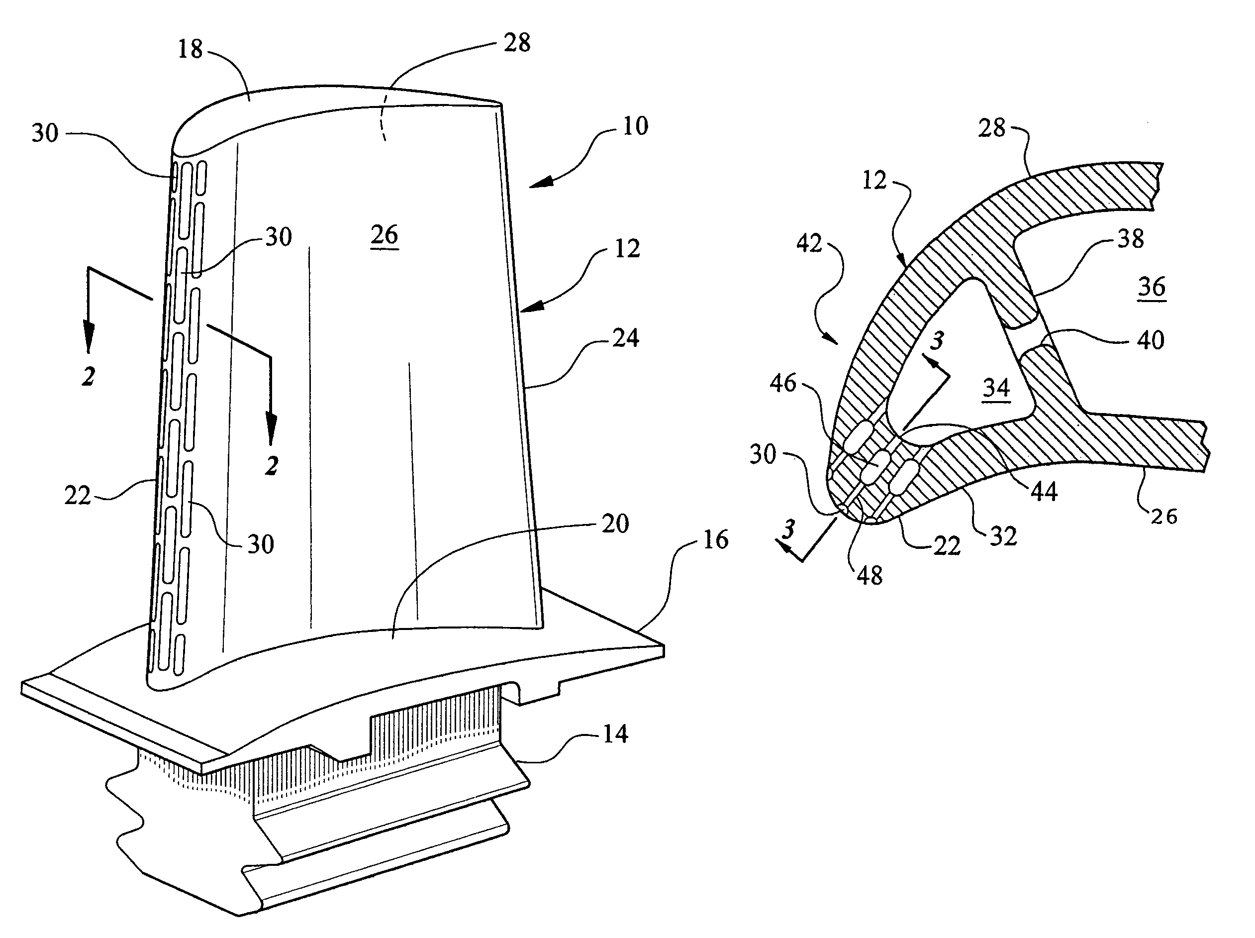
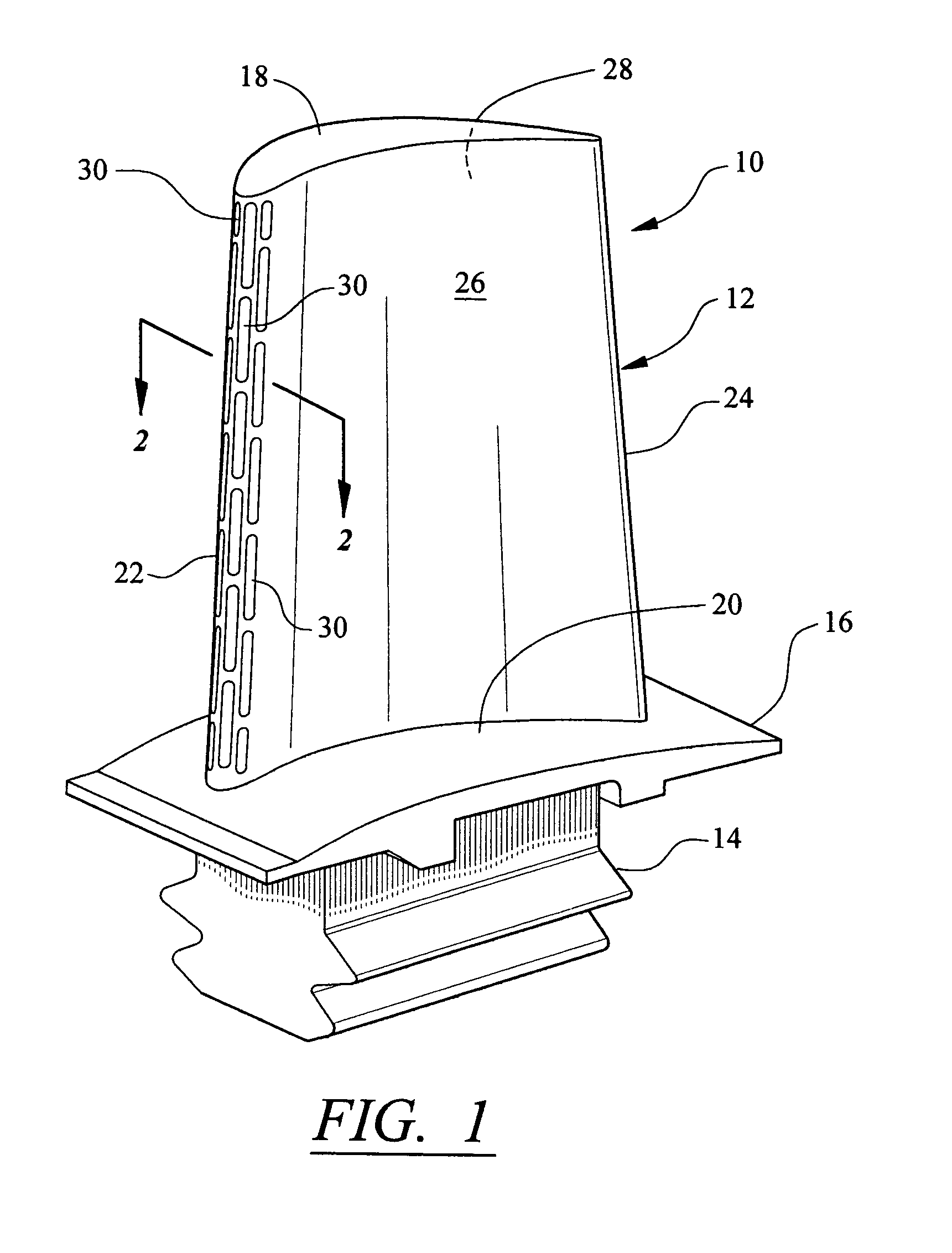
[0019]Reference is now being made to FIG. 1 which illustrates a typical turbine blade for a gas turbine engine generally indicated by reference numeral 10 as comprising an airfoil section 12 and a fir-tree attachment 14 including a platform 16. The airfoil consists of the tip 18, the root 20, the leading edge 22, the trailing edge 24, the pressure side 26 and the suction side 28. A plurality of grooves or pockets 30 forming an array of columns and rows are disposed on the leading edge 22 and these grooves 30 form a portion of this invention and will be described in detail herein below. For the moment, suffice it to say that while the column of grooves extend from the root o...


PUM


Abstract

A plurality of double rows of orifices sandwiching a plenum formed in the wall of the leading edge of an airfoil diffuses the coolant that feeds a plurality of columns and rows of grooves formed in the leading edge of the airfoil so as to diffuse the coolant and define a film of cooling air. The grooves may be aligned or staggered and the orifices, plenums and grooves are sized to match the airflow to the heat load along the leading edge to maximize the use of coolant and enhances engine performance as does the absence of material at the leading edge that results from the use of the columns and rows of grooves.

Description

CROSS-REFERENCE TO RELATED APPLICATION[0001]This application claims benefit of a prior filed now abandoned U.S. provisional application Ser. No. 60 / 454,121, filed on Mar. 12, 2003, entitled MULTI-METERING DIFFUSION COOLING TECHNIQUE by George Liang.[0002]This patent application relates to the contemporaneously filed patent application entitled VORTEX COOLING FOR TURBINE BLADES by the same inventor and commonly assigned to Florida Turbine Technologies, Inc., inasmuch as both inventions relate to cooled turbine blades and both inventions can be utilized together. This application is incorporated herein by reference.STATEMENT REGARDING FEDERALLY SPONSORED RESEARCH OR DEVELOPMENT[0003]NoneTECHNICAL FIELD[0004]This invention relates to air cooled turbines for gas turbine engines and particularly to cooling of the leading edge of the turbine blade.BACKGROUND OF THE INVENTION[0005]This invention constitutes an improvement over U.S. Pat. No. 5,486,093 granted to Auxier et al on Jan. 23, 199...

Claims


Application Information

Patent Timeline
Patent Type & Authority Patents(United States)
IPC IPC(8): F01D5/18B63H1/14
CPCF01D5/182F01D5/186F01D5/187F05D2240/303F05D2240/121
Inventor LIANG, GEORGE
Owner FLORIDA TURBINE TECH
Why Eureka
Try Eureka