Portable lumbar traction device

a lumbar traction device and portable technology, applied in the field of portable lumbar traction devices, can solve the problems of work loss and disability, the most frequent and expensive health care problem, and the force of this magnitude can require special equipment, so as to increase or decrease the tension of the lumbar traction device, increase or decrease the tension, and increase the effect of the spring tension

Active Publication Date: 2006-02-07
STARR DAVID
View PDF21 Cites 29 Cited by
  • Summary
  • Abstract
  • Description
  • Claims
  • Application Information

AI Technical Summary

Benefits of technology

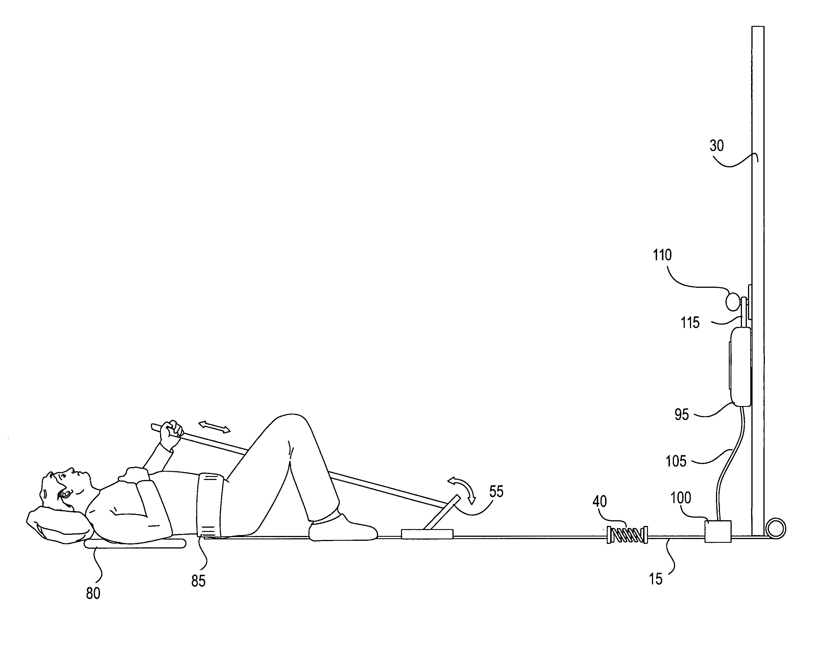
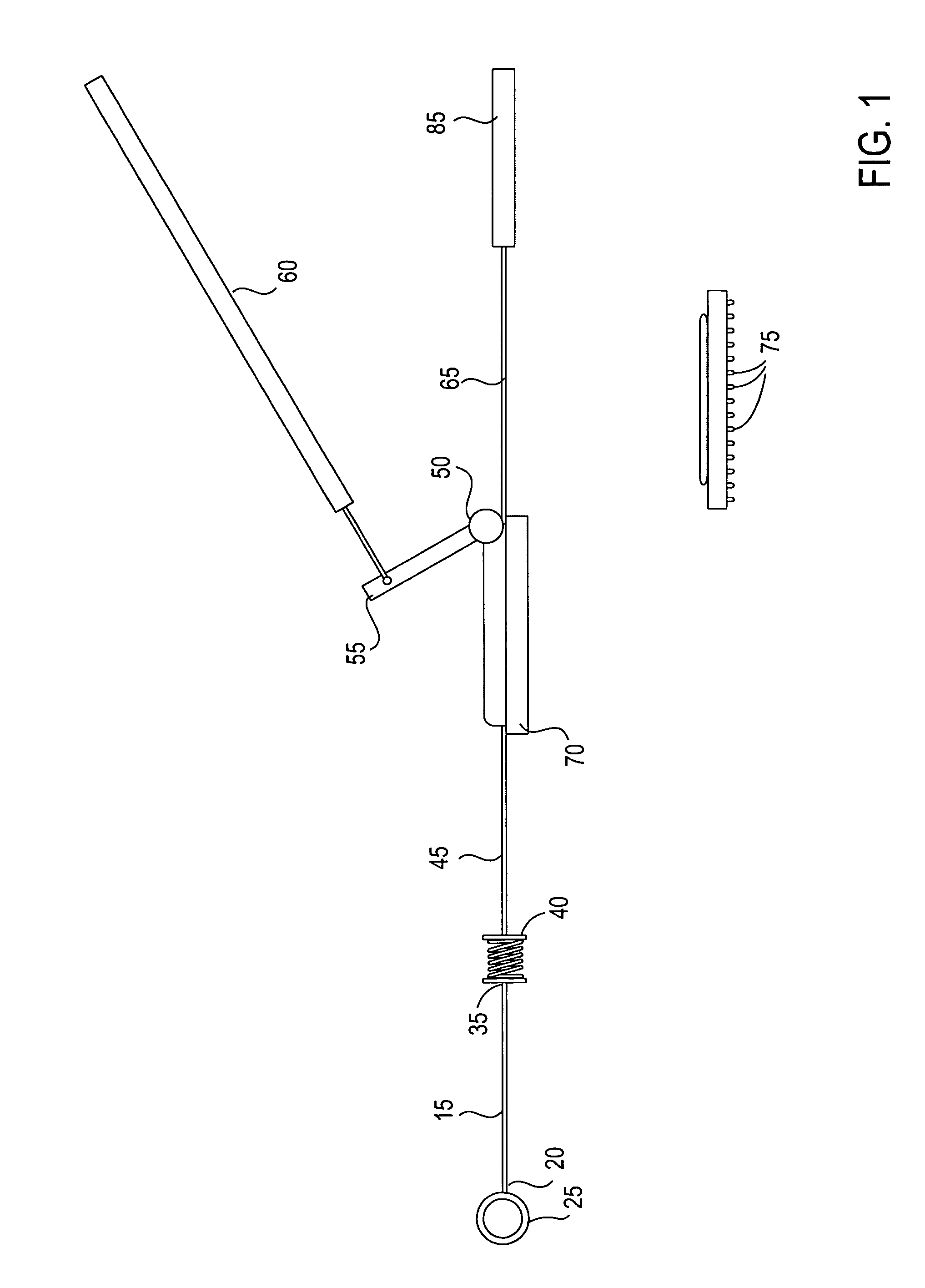
[0005]The present invention is directed to a portable traction device that includes a coiled spring for providing tension to a harness or waist belt worn by the user, and a ratchet operable by the user to adjust the tension applied by the spring. The ratchet may be actuated by a pole or tether controlled by the user to increase or decrease the tension in the lumbar traction device. The spring is further connectable to a door or door frame, post, tree, car bumper, or suitable rigid structure, so that the device is particularly suited for travel or home use. For example, the spring may be connected via a tether to a pipe, block, or the like that is placed on the outside of a closed door with the tether passing underneath the door such that the pipe, block, etc. serves as an ancho

Problems solved by technology

Back pain is the most frequent and expensive health care problem in adults between the ages of 30–50, and is the most common cause of work loss and disability.
Medical science has proven that sitting compresses the spine more than any activity and is a major cause of spinal dysfunction.
Americans are sitting more and more each year, which is a major reason why back pain has become an epidemic and is currently the most expensive medical diagnosis in America—over $100 billion a year.
Forces of this magnitude can require special equipment that is usually limited to doctors and chiropractor's offices.
This can be both inconvenient and expensive for the patient, and unnecessarily crowd therapist's offices while patients undergo lumbar or other tractions.
Currently, the fear of being stranded with back pain keeps countless back pain sufferers restricted in their ability to travel and participate in outdoor activities.
Moreover, the traveler, camper, hiker, golfer, etc. who is in need of relief and away from his practitioner may have to forego treatment due to a lack of available equipment.
Attempts to create a sufficiently low cost portable traction devic

Method used


Image

  • Portable lumbar traction device
  • Portable lumbar traction device
  • Portable lumbar traction device

Examples


Embodiment Construction

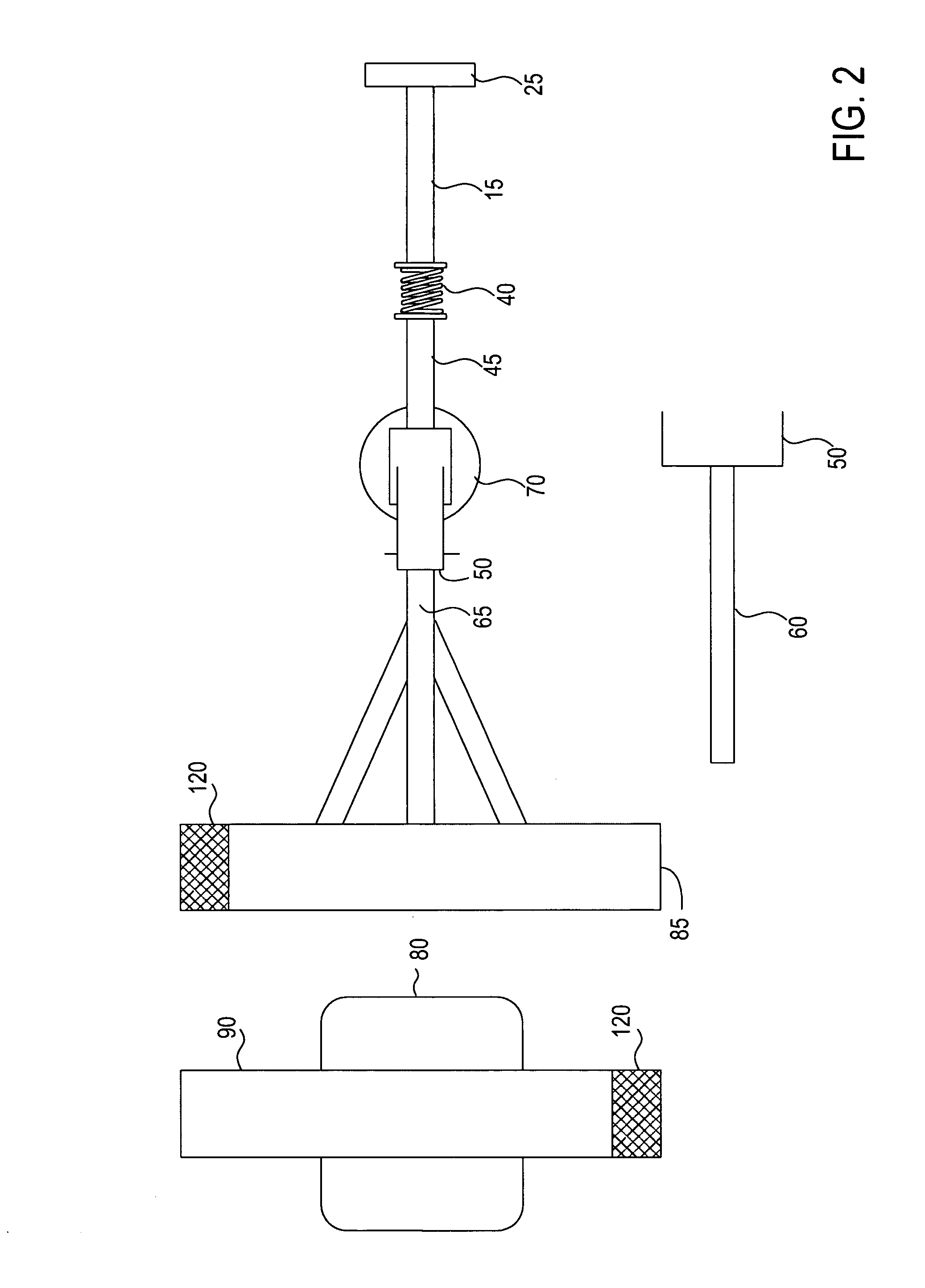
[0009]The present invention is a tensioning device that is portable and capable of mounting or connecting to a common door frame or fixed structure that selectively applies lumbar traction to a patient. The device of the present invention includes an anchoring section that can be used to secure the device to a door frame or the like, a tension producing section that includes a mechanical spring coupled to a ratchet mechanism for increasing the spring's tension, and a belt or harness section that is worn by the user. The belt or harness can be used in conjunction with a pad or mat that incorporates a frictional surface that resists sliding of the pad or mat on the supporting surface such as a carpet, grass, or floor. Each of the three sections will be discussed in turn.

[0010]The anchoring section of the lumbar device in a first embodiment is a non-resilient nylon tether 15 or belt connected at a distal end 20 to a plastic pipe 25 as shown in FIGS. 1 and 2. The pipe 25 is placed behin...


PUM


Abstract

A portable lumbar traction device wherein a variable tension system allows the user to manually manipulate a level of tension using a ratcheting device while undergoing a traction procedure. The invention easily and quickly anchors to a door frame and includes one or more springs to create tension in the device. A belt or harness worn by the user couples to a cable or tether in tension with the spring, and the ratcheting device incrementally increases the tension when actuated by the user until the desired tension level is achieved.

Description

FIELD OF THE INVENTION[0001]The present invention relates generally to apparatus used to treat lower back pain, and more particularly to a portable lumbar traction device used for applying therapeutic tension of varying magnitudes to a patient.BACKGROUND OF THE INVENTION[0002]Back pain is the most frequent and expensive health care problem in adults between the ages of 30–50, and is the most common cause of work loss and disability. Eighty-five percent of the people will suffer some form of back discomfort ranging from intermittent back pain to disability at some time during their lives. For all ages, back pain is the most common cause of activity avoidance (such as golf, gardening, hiking, etc.). Noted back specialists concur that back pain is a symptom of physical dysfunction—i.e., the back is not moving and working as it should. Recovery and relief of pain depends on getting one's back moving and working again and restoring normal function. Medical science has proven that sitting...

Claims


Application Information

Patent Timeline
IPC IPC(8): A61F5/00
CPCA61H1/0292A61H1/0218A61H2203/0456A61H2201/163
Inventor STARR, DAVID
Owner STARR DAVID
Why Eureka
Try Eureka