Prosthetic implant

a prosthetic and implant technology, applied in the field of prosthetic implants, can solve the problems of difficult extrication from their cemented position within the bone, inability to provide optimal load transfer to the surrounding bone structure in use, etc., to enhance the compression or pressurization and thickness distribution of the cement mantle, and enhance the fit of the implant within the bone. , the effect of improving the stress distribution to the bon

Inactive Publication Date: 2006-02-07
HOWIE
View PDF48 Cites 18 Cited by
  • Summary
  • Abstract
  • Description
  • Claims
  • Application Information

AI Technical Summary

Benefits of technology

[0028]Thus, in a preferred embodiment of the invention, the stem portion is adapted to enhance the distribution of stress through the acrylic cement to the bone graft or bone restoration material inserted within the femur to restore previous bone loss.
[0030]The present invention is therefore advantageously able to provide an elongate bone implant, and a joint prosthesis employing such an implant, having no regions of continuous cross-sectional extent. Rather, the invention is able to provide an implant for a joint prosthesis having a succession or series of tapered regions which enhance the fit of the implant within the bone, and enhance the compression or pressurization and thickness distribution of the cement mantle, while also improving the stress distribution to the bone and graft material for the prosthesis. Furthermore, the invention is able to provide an implant for a joint prosthesis having a succession or series of tapers which make the implant more easily removable. This is particularly so in the case of implants having a length greater than 190 mm, for example implants of 200 mm, 205 mm, 220 mm, 230 mm, 240 mm, 260 mm, 280 mm, 300 mm or even greater lengths.
[0031]It should be noted that the present invention does, however, also have application in standard or shorter length bone implants where the bones of the particular patient concerned have a relatively wide proximal cross-section but a relatively narrow more distal region. Prosthetic bone implants having a series of tapered regions according to the present invention may be designed to more optimally occupy or fill a bone having very narrow more distal dimensions.

Problems solved by technology

A disadvantage of femoral implants with stem portions having a constant cross-sectional extent is that the constant cross-section part does not provide optimum transfer of loads to the surrounding bone structure in use.
A further disadvantage of such implants is that they can be harder to extricate from their cemented position within the bone, in the event that the position or orientation of the implant requires revision at some later stage in the life of the prosthetic joint.

Method used


Image

  • Prosthetic implant
  • Prosthetic implant

Examples


Embodiment Construction

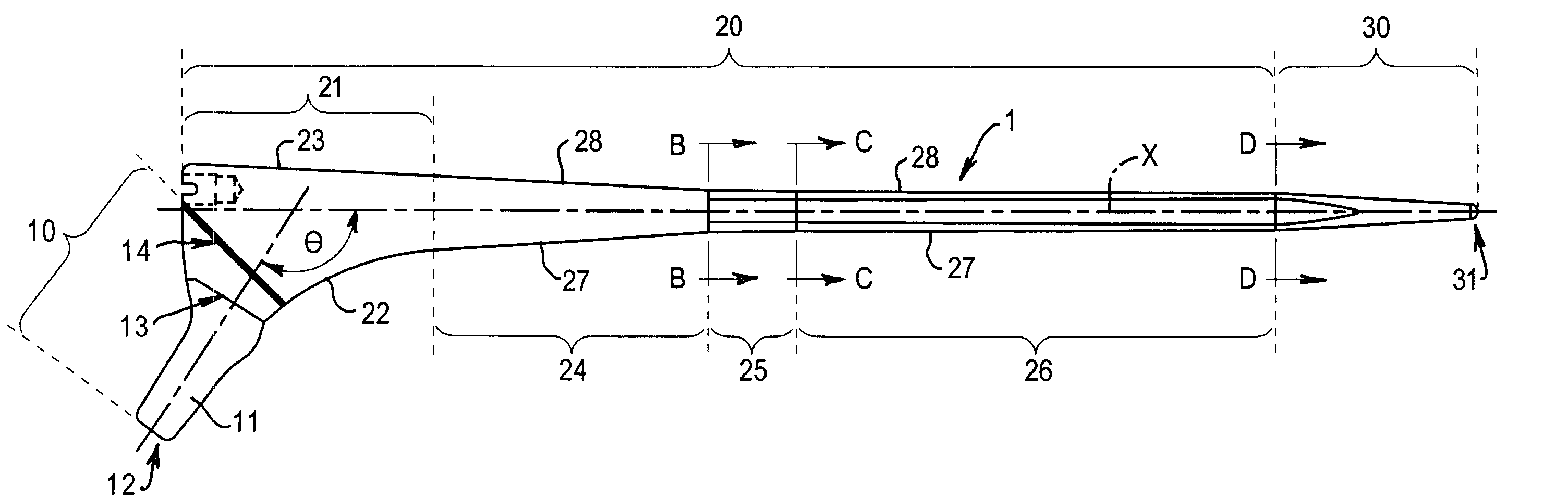
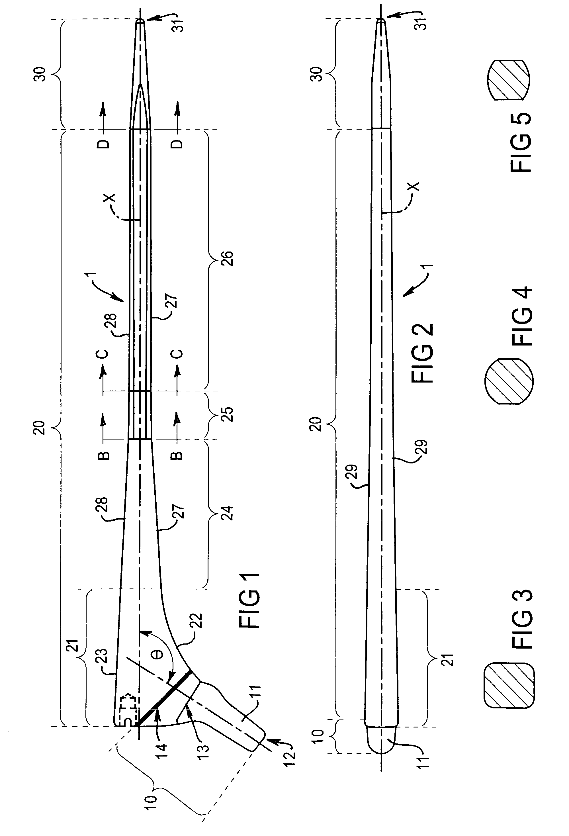
[0038]Referring to FIG. 1 of the drawings, the invention provides an integrally formed elongate femoral implant (1) having a proximal neck portion (10), an elongate stem portion (20) extending distally from the neck portion (10) and a distal tip portion (30). The implant (1) is for insertion within the intramedullary canal of a femur during hip-replacement surgery.

[0039]The proximal neck portion (10) includes a frusto-conical stub (11) projecting at the most proximal end region of the neck portion. This stub (11) has a free end (12) and continues from its other end (13) to join with the stem portion (20). A line (14) across the neck portion (10) effectively marks the extent of the neck portion, which in use projects from the proximal end of the femur. This line (14) also marks the point to which cement is applied when the implant is embedded in the femur.

[0040]The stub (11) provides means for attaching a ball-joint articulation device (not shown). Specifically, this conical stub (11...


PUM


Abstract

A highly polished femoral implant (1) has a proximal neck portion (10), a distal tip portion (30), and an elongate stem portion (20) that extends from the neck portion to the tip portion. The stem portion (20) has a proximal or metaphyseal end region (21) which adjoins the neck portion (10), the proximal / metaphyseal end region (21) having a profile in the medio-lateral plane defined by a curved or angled medial outer contour and a curved or straight lateral outer contour. The stem portion (20) of the implant has a first part (24) adjacent said send region (21) having a profile in the medio-lateral plane which tapers distally at a first angle of taper to a region intermediate the length of the stem portion, and a second part (25,26) distal of the first part (24) having a profile in the medio-lateral plan which tapers distally at a second angle of taper from the region intermediate the length of the stem portion.

Description

FIELD OF THE INVENTION[0001]The present invention relates generally to prostheses, and more particularly to an implant for a bone or joint prosthesis.[0002]The invention has particular application to femoral implants for hip prostheses and it will be convenient to hereinafter describe the invention in this exemplary context. It should be appreciated, however, that the invention is not limited to this particular application, but is suitable for use in a range of other bones and joints. For example, the invention may also be suitable for knee, shoulder and elbow prostheses and may therefore include an implant for the tibia or humerus.BACKGROUND OF THE INVENTION[0003]Prostheses for use in total hip replacement typically include an elongate member for implantation in the femur. This implant member typically includes a distal tip portion for location deep within the bone, a proximal neck portion for providing articulation of the joint prosthesis and an elongate stem portion which extends...

Claims


Application Information

Patent Timeline
Patent Type & Authority Patents(United States)
IPC IPC(8): A61F2/36A61F2/32A61F2/00A61F2/28A61F2/30A61F2/46
CPCA61F2/3662A61F2/30724A61F2310/00029A61F2/367A61F2/3672A61F2/3676A61F2/4607A61F2002/2835A61F2002/30112A61F2002/30153A61F2002/3021A61F2002/30322A61F2002/30332A61F2002/30616A61F2002/30617A61F2002/30813A61F2002/3625A61F2002/365A61F2002/4631A61F2220/0033A61F2230/0004A61F2230/0019A61F2230/0067A61F2250/0026A61F2250/0097A61F2310/00017A61F2310/00023A61F2/36
Inventor HOWIE, DONALD W.
Owner HOWIE
Why Eureka
Try Eureka