Push-on switch

a push-on switch and switch body technology, applied in the direction of snap-action arrangements, contact surface shapes/structures, movable contacts, etc., can solve the problem of limited switch width reduction, and achieve the effect of reducing the switch width and ensuring conduction

Active Publication Date: 2006-02-07
HOSIDEN CORP
View PDF12 Cites 51 Cited by
  • Summary
  • Abstract
  • Description
  • Claims
  • Application Information

AI Technical Summary

Benefits of technology

[0012]According to the invention, the upper movable contact is formed into an oval dome-like shape which is obtained by cutting away both ends of a circular dome-like movable contact in the conventional art. Therefore, it is possible to obtain a two-step push-on switch in which reduction of the dimensions of the switch, particularly the width can be realized while ensuring the operation stroke of the movable contact, and which has a reduced width that enables the switch to be mounted even in a side face of a thin apparatus such as a portable telephone. In the upper movable contact having an oval dome-like shape, even when the central area is largely displaced as a result of depression, a stress produced in the movable contact is more relaxed as compared with that applied to a circular dome-like movable contact in the conventional art. Therefore, the invention can provide a two-step push-on switch which can attain effects such as that occurrence of failures such as cracks or deflection is suppressed, that the life number of ON / OFF operations is remarkably increased, and that the life period is longer than that of a conventional switch.
[0013]In the case where the switch is configured so that the movable contacts are fixed in an invertible manner to the body respectively by adhesive sheets each of which is bonded from the side of the upper face of corresponding one of the movable contacts, the through hole is formed in the central area of the adhesive sheet which fixes the lower movable contact to the body, the downward projection is disposed in the central area of the upper movable contact, and the upper face of the top portion of the lower movable contact is exposed through the through hole of the adhesive sheet, thereby enabling the upper face to be contacted with the projection of the upper movable contact, the upper movable contact and the lower movable contact can be directly contacted with each other so as to attain electrical conduction, although the lower movable contact is simply bonded and fixed to the body by the adhesive sheet. Moreover, the downward projection disposed in the central area of the upper movable contact plays the role of a support member which, in the conventional art, is disposed as another member in a central area between upper and lower movable contacts in order to definitely obtain senses of two-step operations. Therefore, it is possible to obtain excellent senses without increasing the number of parts. Consequently, this configuration is effective.
[0015]In the case where, in the upper movable contact, the legs are elongated continuously from four corners of the oval portion which is invertible, the leg accommodating recesses which accommodate the legs of the upper movable contact are formed in four corners of the body to be continuous to the recess, respectively, and the stationary contact which is always in contact with at least one of the legs is disposed in the leg accommodating recesses, the legs are provided with a spring property, thereby enabling the movable contact to be always in electric contact with the stationary contact (the second peripheral stationary contact) in both a no-load condition (both the first- and second-step switches are turned OFF) and a case where a load causing a large displacement amount is applied (the second-step switch is turned ON). When the stationary contact is grounded, a sure countermeasure against static electricity can be performed, and hence the invention is effective.
[0016]When the legs elongate from the four corners of the invertible oval portion to be continuous in the longitudinal direction of the oval portion, sure conduction can be attained while realizing reduction of the width of the switch. Consequently, this configuration is further effective.

Problems solved by technology

When a dome-like cross plate spring is used as an upper movable contact as described above, a square accommodating space is required, and hence size reduction of the width of a switch is limited from the viewpoint of a shape.

Method used


Image

  • Push-on switch
  • Push-on switch
  • Push-on switch

Examples


Embodiment Construction

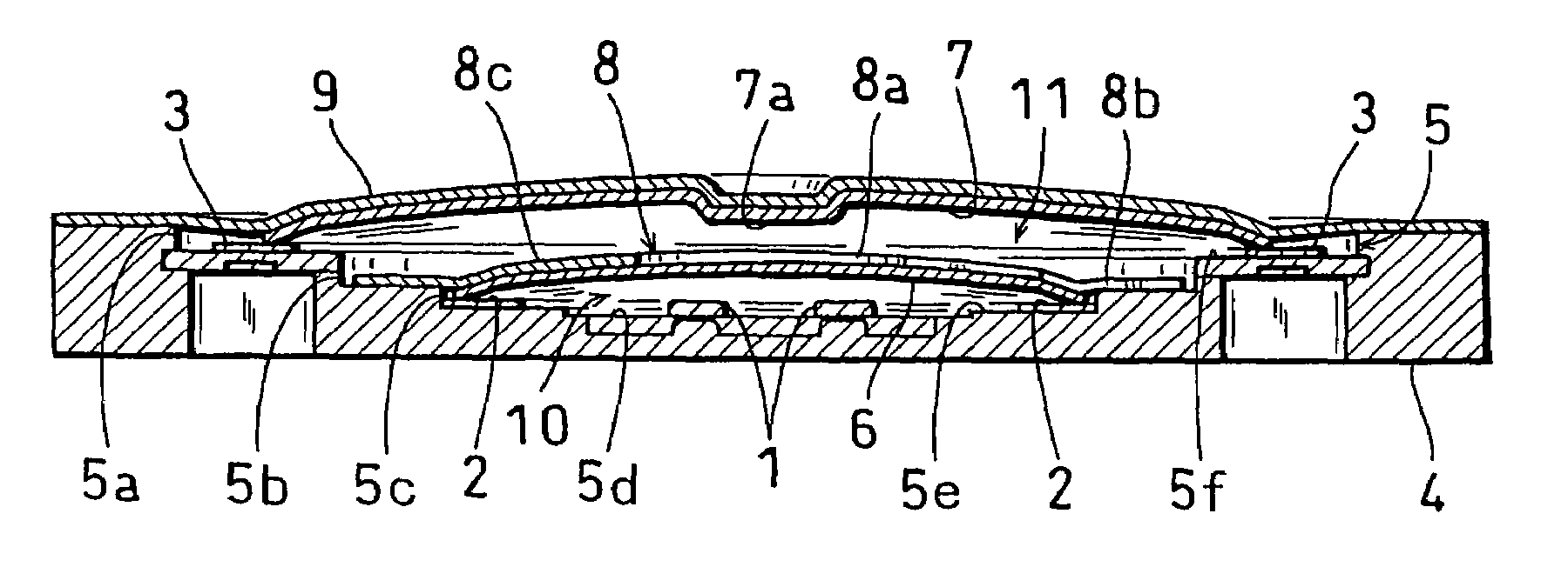
[0022]In a push-on switch in which a dome-like movable contact is inverted as a result of a depressing operation to make electrical conduction, and more particularly in a two-step push-on switch into which two or upper and lower movable contacts are incorporated, a two-step push-on switch structure was realized in which the operation sense can be improved while improving the durability of the upper movable contact and reducing the number of parts, and the width of the switch is reduced while ensuring the operation stroke of the movable contact.

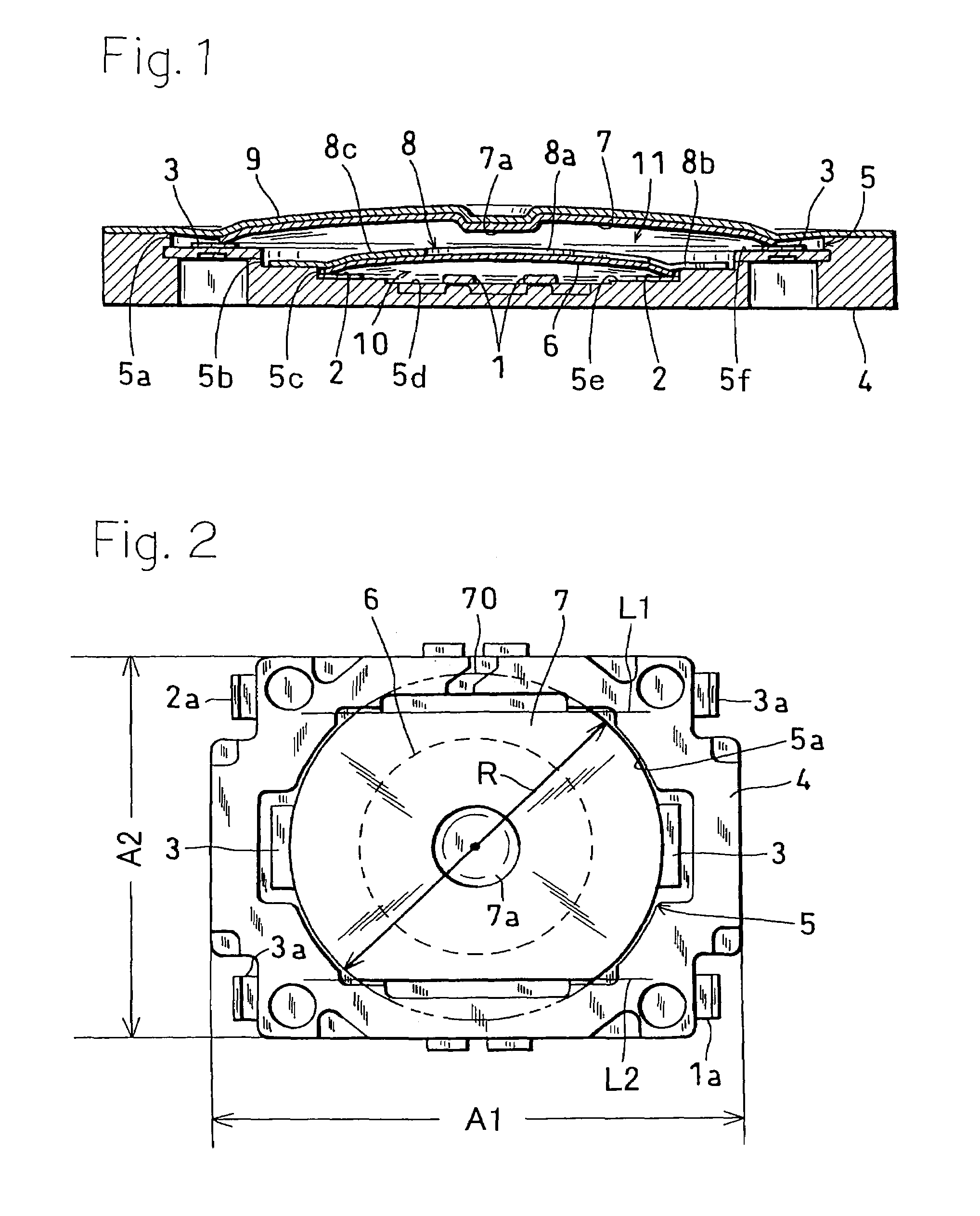
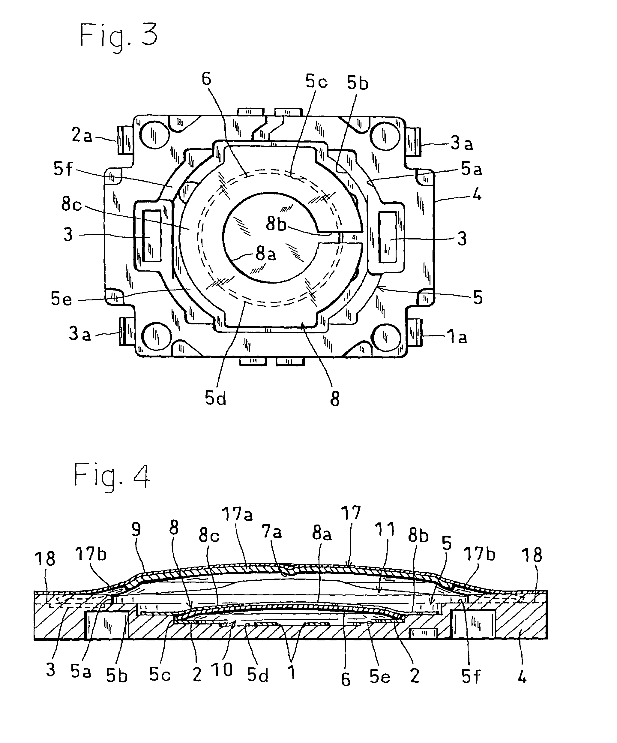
[0023]Hereinafter, a first embodiment of the invention will be described with reference to FIGS. 1 to 3. FIG. 1 is a section view of a push-on switch of the first embodiment, FIG. 2 is a plan view showing a state where an upper adhesive sheet in the switch shown in FIG. 1 is removed away, and FIG. 3 is a plan view showing a state where an upper movable contact in the switch shown in FIG. 2 is removed away.

[0024]The push-on switch of the embodi...


PUM


Abstract

A two-step push-on switch in which the operating stroke of an upper movable contact is ensured, and particularly the width of the switch is reduced while the durability of the upper movable contact is improved, the number of parts is reduced, an the operation is improved. Dome-like movable contacts are placed in two or upper and lower stages in an invertible manner in a recess of an insulative body having a plurality of stationary contacts, and the upper movable contact is formed into an oval shape.

Description

BACKGROUND OF THE INVENTION[0001]1. Field of the Invention[0002]The present invention relates to a push-on switch in which a dome-like movable contact is inverted as a result of a depressing operation to make electrical conduction, and more particularly to a two-step push-on switch into which two or upper and lower movable contacts are incorporated.[0003]2. Description of the Prior Art[0004]In a two-step push-on switch into which two or upper and lower movable contacts are incorporated, usually, circular dome-like plate springs are used as the movable contacts. In this case, in order to increase the operation stroke, the movable contacts must have a large external shape, thereby producing a problem in that the whole size of the switch is increased. In a two-step push-on switch, the upper movable contact itself conducts an inverting operation, and a central portion is displaced to a position where the lower movable contact conducts an inverting operation. Therefore, a stress produced...

Claims


Application Information

Patent Timeline
Patent Type & Authority Patents(United States)
IPC IPC(8): H01H5/30H01H13/66H01H13/48H01H13/52H01H13/64
CPCH01H13/48H01H13/64H01H2205/026
Inventor ASADA, MAKOTO
Owner HOSIDEN CORP
Why Eureka
Try Eureka