
Dynamic backup routing of network tunnel paths for local restoration in a packet network

a packet network and tunnel path technology, applied in the field of routing packets in the telecommunications network, can solve the problems of delay, end-to-end restoration may have an unnecessarily long delay before switching from the primary to the secondary path, etc., and achieve the effect of minimizing costs

Active Publication Date: 2006-02-07
LUCENT TECH INC
View PDF11 Cites 86 Cited by
  • Summary
  • Abstract
  • Description
  • Claims
  • Application Information

AI Technical Summary

Benefits of technology

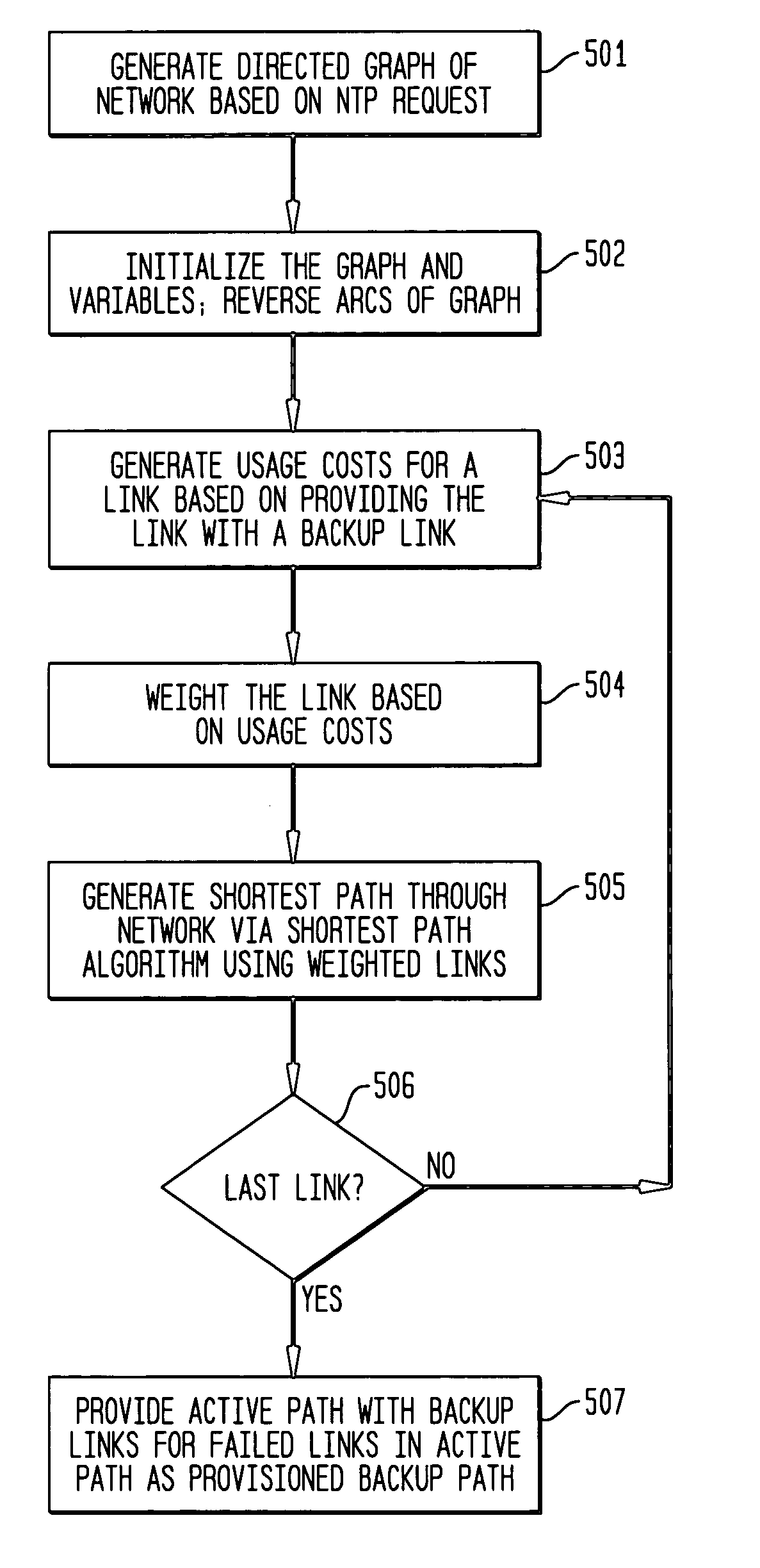
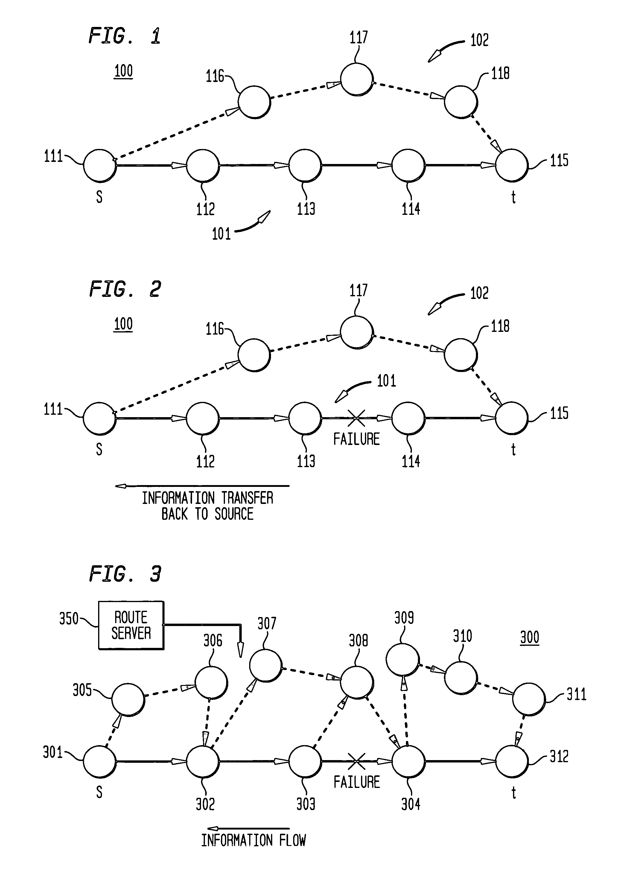
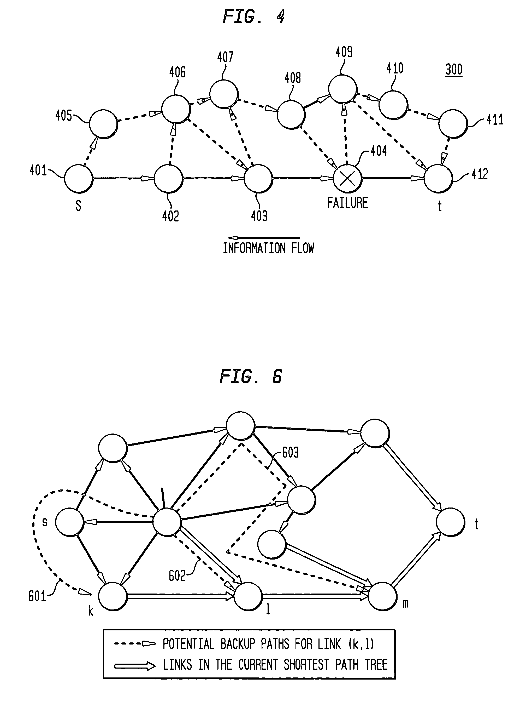
[0014]In accordance with embodiments of the present invention, a packet network of interconnected nodes employs dynamic backup routing of a Network Tunnel Path (NTP) request. Dynamic backup routing allocates an active and backup path to the NTP. Dynamic backup routing employs a local restoration model to determine the allocation of, and, in operation, to switch between, a primary (also termed active) path and a secondary (also termed backup) path based upon detection of a network failure. Switching from the active path is based on a backup path determined with iterative shortest-path computations with link weights assigned based on the cost of using a link to backup a given link in the active path. Costs may be assigned based on single-link failure or single element (node or link) failure. Link weights are derived by assigning usage costs to links for inclusion in a backup path, and minimizing the costs with respect to a predefined criterion. For single-link failure, each link in the active path has a corresponding disjoint link in the backup path. For single-element failure, in addition to backup of the final link in the active path, all links incident have disjoint bypass links assigned to account for node failure. While intra-demand sharing is used, inter-demand sharing may also be provided if complete network information is available for dynamic backup routing.

Problems solved by technology

However, this approach in end-to-end restoration may have an unnecessarily long delay before switching from the primary to secondary path.
This delay may occur because information has to propagate back to the source, which in turn switches from the primary to the secondary path for all the demands that use the link.

Method used


Image

  • Dynamic backup routing of network tunnel paths for local restoration in a packet network
  • Dynamic backup routing of network tunnel paths for local restoration in a packet network
  • Dynamic backup routing of network tunnel paths for local restoration in a packet network

Examples


Embodiment Construction

[0023]In accordance with embodiments of the present invention, dynamic backup routing of a Network Tunnel Path (NTP) allocates an active and backup path to the NTP based upon detection of a network failure. Dynamic backup routing employs local restoration to determine the allocation, and, in operation, to switch between a primary (also termed active) path and a secondary (also termed backup) path. In local restoration, nodes on either end of one or more failed links switch traffic to a backup path. Switching from the active path is based on a backup path determined with iterative shortest-path computations with link weighting based on the cost of using a link to backup a given link for either single-link failure or single element (node or link) failure. Active and Back-up paths generated in accordance with embodiments of the present invention may provide for local restoration with relatively short delay in switching to a backup path.

[0024]In local restoration, when an element (a nod...


PUM


Abstract

A packet network of interconnected nodes employing dynamic backup routing of a Network Tunnel Path (NTP) allocates an active and backup path to the NTP based upon detection of a network failure. Dynamic backup routing employs local restoration to determine the allocation of, and, in operation, to switch between, a primary / active path and a secondary / backup path. Switching from the active path is based on a backup path determined with iterative shortest-path computations with link weights assigned based on the cost of using a link to backup a given link. Costs may be assigned based on single-link failure or single element (node or link) failure. Link weights are derived by assigning usage costs to links for inclusion in a backup path, and minimizing the costs with respect to a predefined criterion.

Description

CROSS-REFERENCE TO RELATED APPLICATIONS[0001]This application claims the benefit of the filing date of U.S. provisional application Nos. 60 / 216,394, filed on Jul. 6, 2000, and 60 / 239,771, filed on Oct. 12, 2000.BACKGROUND OF THE INVENTION[0002]1. Field of the Invention[0003]The present invention relates to routing packets in a telecommunications network, and, more particularly, to determining paths through nodes of the network for dynamic backup routing of packets for restoration.[0004]2. Description of the Related Art[0005]In interconnected packet networks, such as the Internet, users establish a connection between a source and a destination with a stream of data packets (called a “packet flow” or “flow”) transferred through the network over a network path. The network path is defined by a set of nodes interconnected by a set of links through which packets of the connection are transferred. Packet networks may have a hierarchical structure in which smaller networks are interconnect...

Claims


Application Information

Patent Timeline
IPC IPC(8): G01R31/08H04L12/56
CPCH04L45/12H04L45/28H04L45/22H04L45/123
Inventor KODIALAM, MURALIDHARAN S.LAKSHMAN, TIRUNELL V.
Owner LUCENT TECH INC
Learn More