Increased height inflatable support system

a support system and height technology, applied in the field of inflatable support systems, can solve the problems of poor air retention, clunky air mattress design, poor comfort of the mattress, etc., and achieve the effect of increasing the surface area

Inactive Publication Date: 2006-02-14
THE COLEMAN CO INC
View PDF37 Cites 27 Cited by
  • Summary
  • Abstract
  • Description
  • Claims
  • Application Information

AI Technical Summary

Benefits of technology

[0017]In a fifth embodiment of the present invention, an inflatable mattress is provided. The inflatable mattress has at least two or more inflatable chambers wherein each inflatable chamber comprises a plurality of elongated parallel channels that extend in a longitudinal direction and that are in fluid communication with one another. A means for increasing the surface area across which weight added to the support system can be distributed is also provided.

Problems solved by technology

While air mattresses are a significant improvement over sleeping on the ground or curled up on a sofa, the mattresses still have many problems.
For example, air mattress designs were clunky and uncomfortable, the manufacturing techniques and materials used resulted in poor air retention, the inflation and deflation systems employed with such mattresses often required significant time and effort, and the mattresses tended to provide only marginal support.
Furthermore, getting into and out of such a bed can be difficult, especially for an elderly or disabled person.
But, such inflatable mattresses have a propensity to roll over.
Rollovers are not only a problem with inflatable mattresses, but with all lightweight support surfaces, such as inflatable furniture.
While this approach has some merit, the introduction of separately inflatable tubes means added work for the consumer, who must move an inflation device from one valve to another until the chair is properly filled.
However, such strengthening is only provided to areas adjacent to the tubes.
While this may be practical for inflatable support systems with smaller weight bearing surfaces, such as chairs, a few, relatively short stabilizer bars will not provide stability for larger inflatable support systems, such as inflatable mattresses.
An additional problem faced by inflatable support systems of the prior art is structural stability of the sides of the support system.
Such distortion can cause a person to slip or fall from the support surface, increasing the risk of injury to a user.
This problem becomes increasingly significant as the height of the support system is increased.

Method used


Image

  • Increased height inflatable support system
  • Increased height inflatable support system
  • Increased height inflatable support system

Examples


Embodiment Construction

[0029]Reference will now be made in detail to the preferred embodiments of the present invention, examples of which are illustrated in the accompanying drawings.

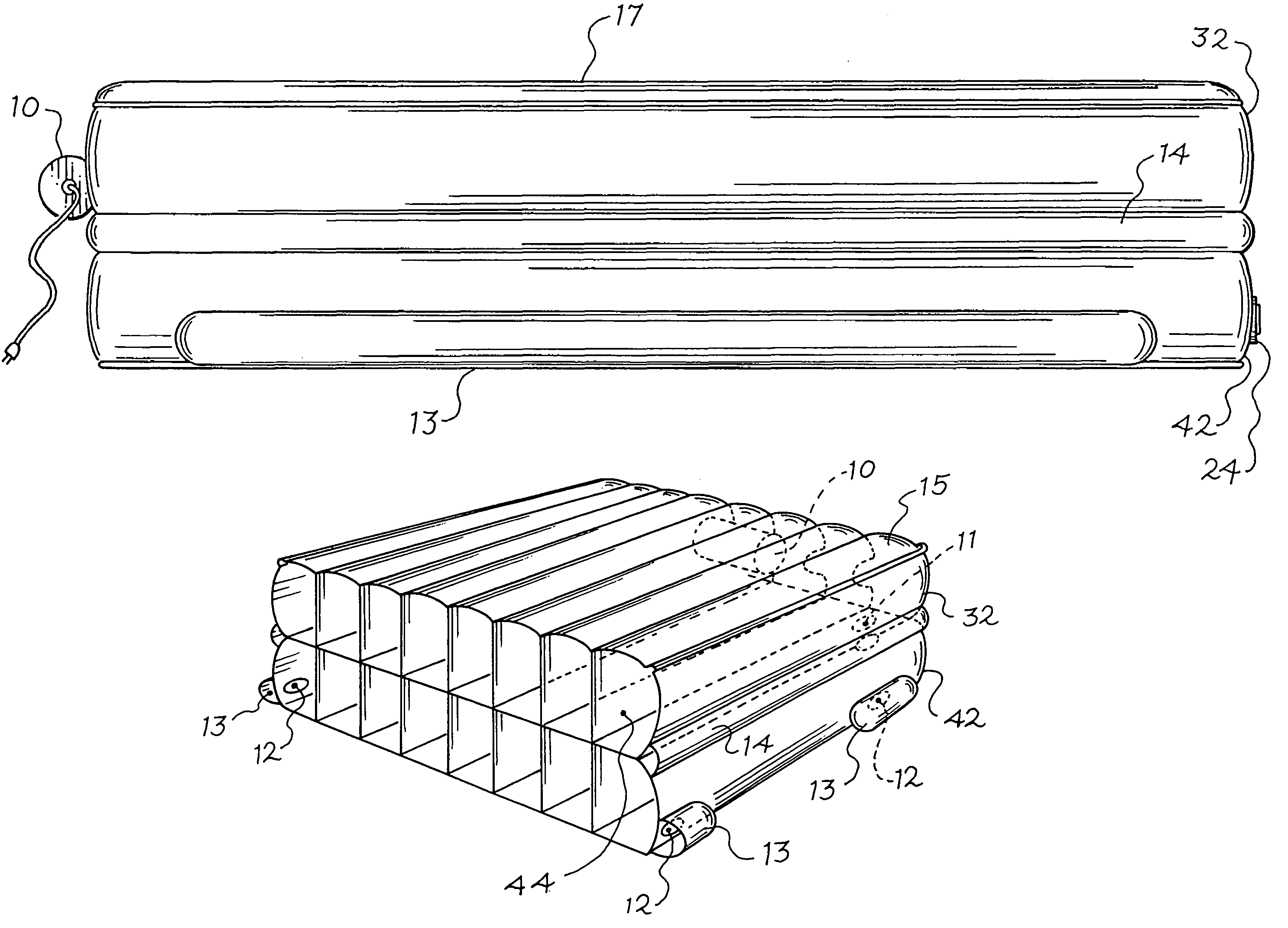
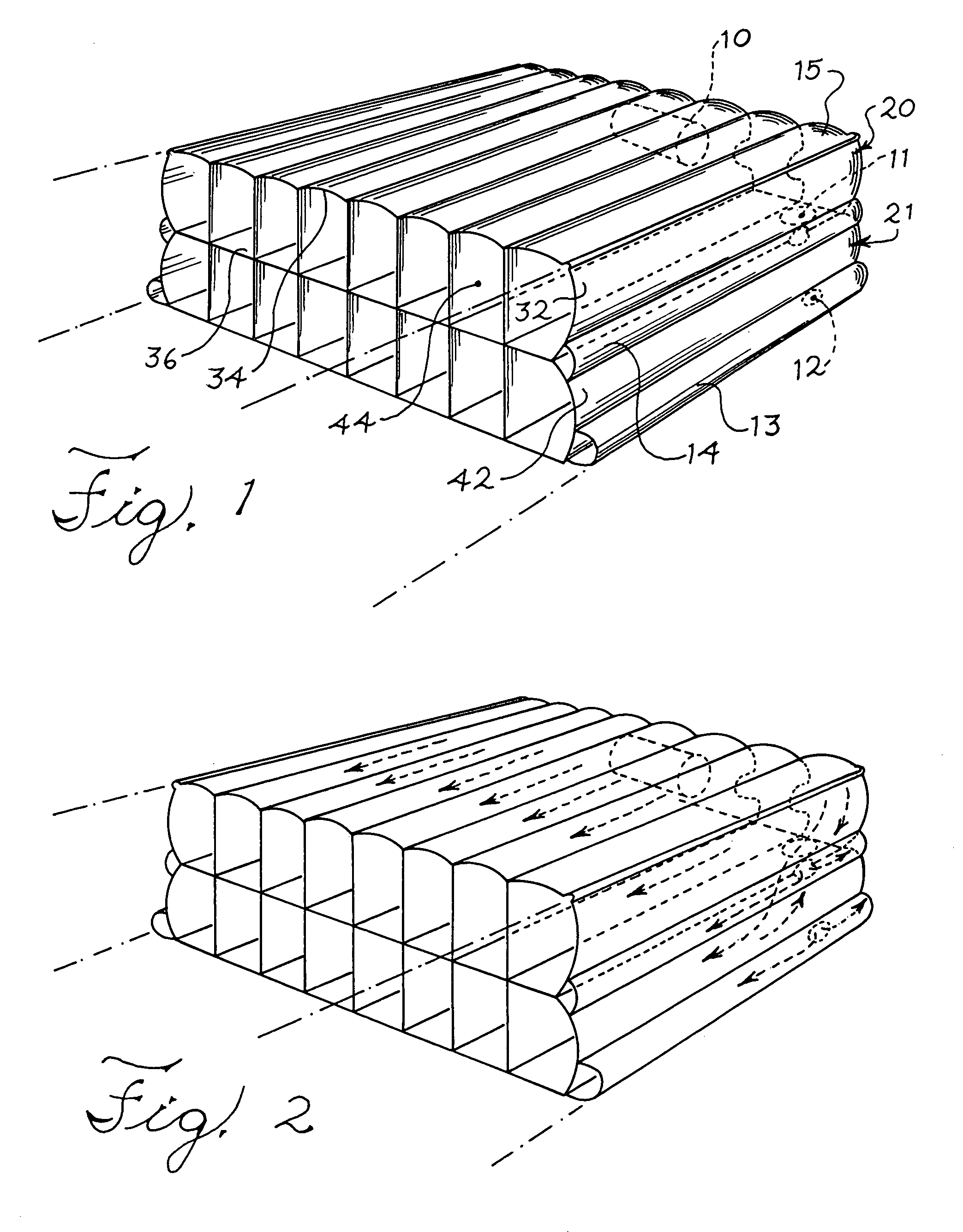
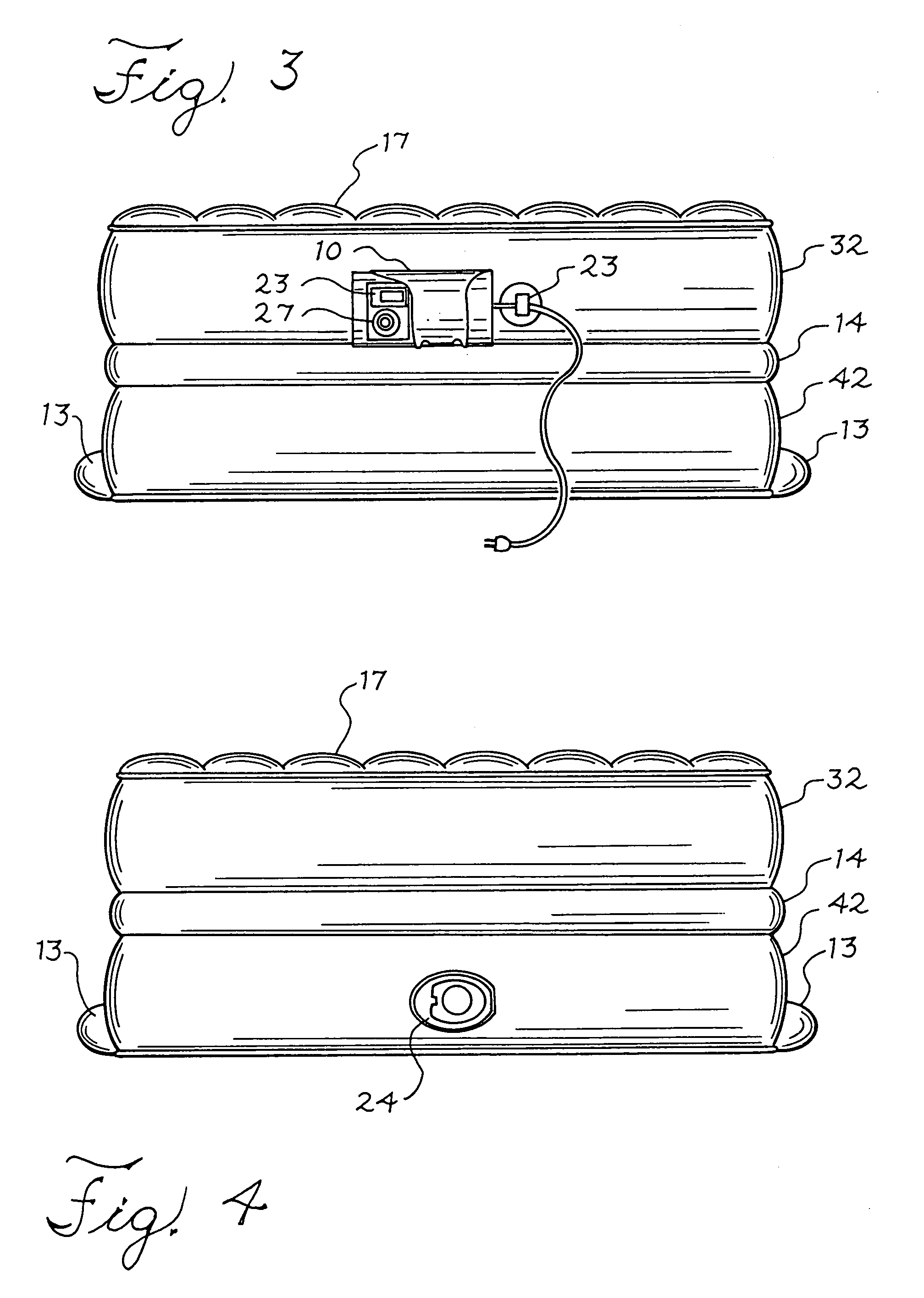
[0030]FIG. 1 is a perspective view of the internal structure of an inflatable mattress embodiment of the present invention. FIG. 1 illustrates an embodiment comprising an inflatable support system including two support chambers 20, 21, stacked vertically. In the embodiment illustrated in FIG. 1, the upper support chamber 20 is constructed with side gussets 32 approximately ten inches high, which connect to top 34 and bottom 36 layers. The lower support chamber 21 is constructed from a top layer 38, a bottom layer 40 and a side gusset 42 that is approximately fifteen inches high. It should be clear to one skilled in the art that alternative side gusset heights and chamber arrangements could be substituted without departing from the spirit and scope of the present invention. By way of example, FIG. 7 illustrates the use of mul...


PUM


Abstract

An inflatable mattress is provided having an upper and a lower inflatable support chamber which are arranged in a substantially vertical manner. Each inflatable support chamber has a top layer, a bottom layer, and a side gusset. At least one inflatable stabilizing component is attached at the bottom layer of the lower inflatable support chamber and is of a height less than the height of the lower inflatable support chamber.

Description

RELATED APPLICATION DATA[0001]This application is a continuation of U.S. Ser. No. 09 / 918,561, filed Aug. 1, 2001, now U.S. Pat. No. 6,701,559, and entitled “Increased Height Inflatable Support System,” the entire disclosure of which is hereby incorporated by reference.FIELD OF THE INVENTION[0002]The present invention relates to the field of inflatable support systems, which may include air mattresses and inflation controls thereof.BACKGROUND OF THE INVENTION[0003]Most everyone has faced the need for an extra bed or mattress at some time in their life. Air mattresses, originally introduced many years ago, have allowed homeowners and others to provide their guests with a surface more comfortable than sleeping on the floor, while not imposing the same storage requirements as traditional mattresses.[0004]While air mattresses are a significant improvement over sleeping on the ground or curled up on a sofa, the mattresses still have many problems. For example, air mattress designs were cl...

Claims


Application Information

Patent Timeline
Patent Type & Authority Patents(United States)
IPC IPC(8): A47C27/10A47C27/08
CPCA47C27/082A47C27/10A47C27/087
Inventor BOSO, KAREN L.CHING-CHIN, CHEN
Owner THE COLEMAN CO INC
Why Eureka
Try Eureka