Diesel combustion chamber

Active Publication Date: 2006-02-14
INT ENGINE INTPROP CO LLC
View PDF35 Cites 68 Cited by
  • Summary
  • Abstract
  • Description
  • Claims
  • Application Information

AI Technical Summary

Benefits of technology

[0007]The piston of the present invention substantially meets the aforementioned needs of the industry. The combustion chamber of the present invention defined intersecting the crown of the piston has been shown by substantiated simulation to greatly increase turbulence kinetic energy to the chamber and thereby to both reduce soot entrainment and NOx emissions as compared to a known combustion chamber. The piston has been shown to functi

Problems solved by technology

The amount of soot that is expelled with the engine's exhaust is unsightly and generates public pressure to clean up diesel engines.
Further, the amount of soot that is entrained in the engine's lubrication oil can have a deleterious effect on engine re

Method used


Image

  • Diesel combustion chamber
  • Diesel combustion chamber
  • Diesel combustion chamber

Examples


Example

DETAILED DESCRIPTION OF THE DRAWINGS

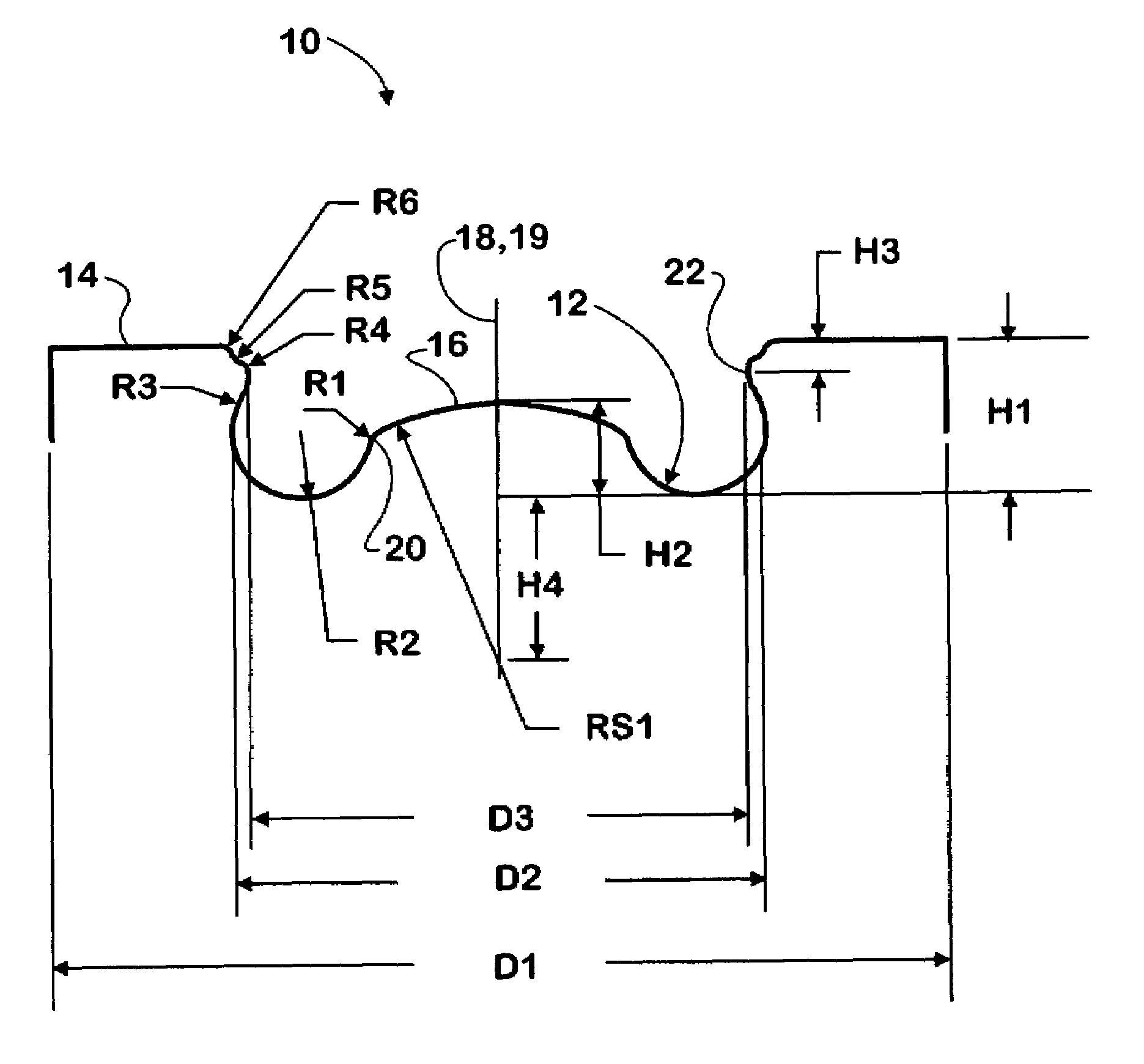
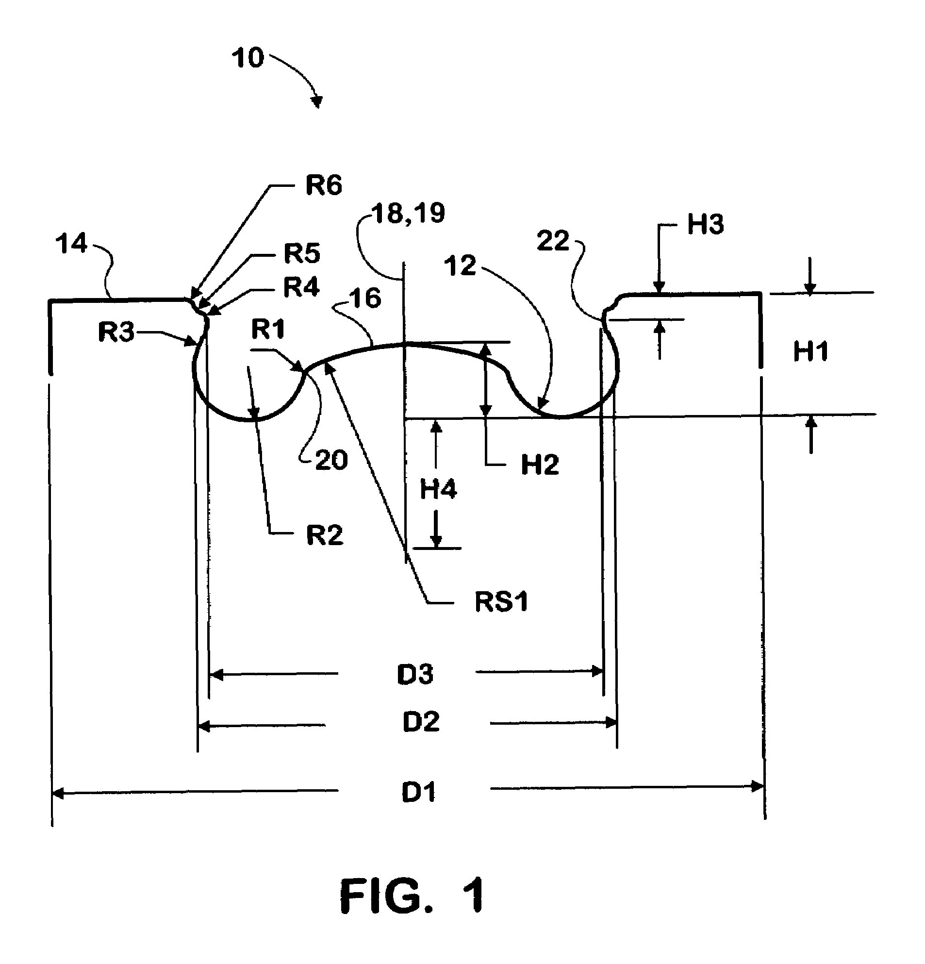
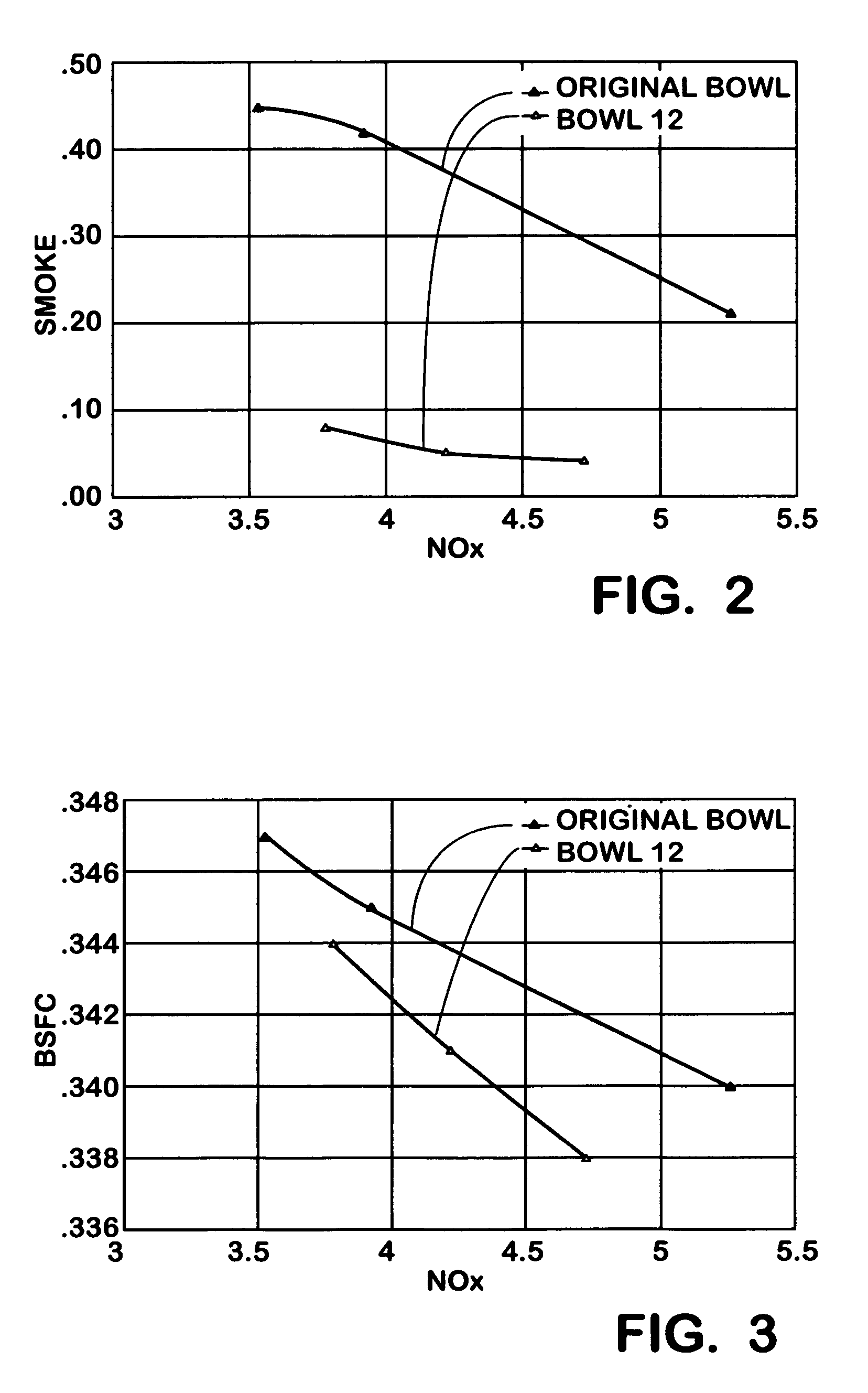
[0018]The piston of the present invention is shown generally at 10 in FIG. 1. Generally, the piston 10 has a centrally located symmetrical upward-opening chamber bowl assembly for forming a combustion chamber 12 in cooperation with cylinder structure within a cylinder of a diesel engine. The combustion chamber 12 is defined intersecting the crown 14 of the piston 10. The engine has a fuel injector (not shown) disposed generally above the piston 10 for forming a downward directed injected fuel plume relative to the combustion chamber 12. The piston 10 may be utilized with two-valve or multiple-valve heads. The piston 10 is effective for reducing diesel engine pollutant emissions, such as NOx and soot, as depicted in the graphic representations of FIGS. 2–9. The piston 10 is preferably applicable to heavy-duty and medium duty diesel engines.

[0019]A combustion chamber located in a piston of diesel engines generally is comprised of a bottom portion an...


PUM


Abstract

A combustion chamber assembly for use in a diesel engine includes a combustion chamber being defined intersecting a crown of a piston, the combustion chamber being defined by a first curved surface having a reentrancy formed proximate a first curved surface first end and having a post formed proximate a first curved surface second end, a corner being formed at a juncture of the first curved surface second end and the post, adjacent surfaces being direct smooth junctures. A piston and a method of forming a combustion chamber are further included.

Description

TECHNICAL FIELD[0001]The present invention relates to a piston designed for use in a compression ignition (diesel) internal combustion engine. More particularly, the present invention relates to a combustion chamber defined in part in a piston and intersecting the crown of the piston.BACKGROUND OF THE INVENTION[0002]Many attempts have been made to produce an ideal flow pattern for the charge of air and fuel within the combustion chamber of a diesel internal combustion engine. Considerations that must be taken into effect include, but are not limited to, providing for adequate power generation, minimizing the NOx entrained in the engine exhaust, and minimizing the amount of soot particulate also entrained in the engine exhaust. These last two considerations should be accomplished without hurting the fuel economy of the engine and without adversely affecting the power output of the engine.[0003]It is known that changes in any one of a variety of engine design / operating variables, such...

Claims


Application Information

Patent Timeline
IPC IPC(8): F02F3/26
CPCF02B23/0672F02B3/06Y02T10/125Y02T10/12
Inventor LIU, ZHENGBAI
Owner INT ENGINE INTPROP CO LLC
Why Eureka
Try Eureka