Method and apparatus for seaming abutting layers of planar material

a technology of planar material and abutting edges, which is applied in the directions of transportation and packaging, liquid transfer devices, carpet fasteners, etc., can solve the problems of abutting edges that cannot be curved, no adhesive is placed between the abutting edges of the floorcovering, and heat produced by the iron to melt the thermoplastic adhesive will melt or burn the floorcovering itself, etc. problem, to achieve the effect of curved seams, the method is difficult to us

Active Publication Date: 2006-02-14
BENO J GUNDLACH
View PDF11 Cites 6 Cited by
  • Summary
  • Abstract
  • Description
  • Claims
  • Application Information

AI Technical Summary

Benefits of technology

[0023]Preferably, the connection means is an elbow-shaped device that can swivel about a vertical axis substantially parallel to the leg passageway. One end of the elbow attaches to the upper end of the leg portion while the other end attaches to the adhesive dispenser. The ability of the elbow to swivel allows the dispenser to rotate out of the way from obstacles, such as a wall, permitting the applicator tip to be used to complete a finished seam in one continuous pass.

Problems solved by technology

One problem with the prior tip is that the adhesive dispenser attached to the prior tip is oriented upwards at an angle leading in the direction that the prior tip follows to form the finished seam.
First, no adhesive is placed between the abutting edges of the floorcovering.
Second, there is a risk that the heat produced by the iron to melt the thermoplastic adhesive will melt or burn the floorcovering itself.
Third, this method is difficult to used when making finished seams that are curved.
The bulkiness of the backing tape with thermoplastic adhesive makes the tape difficult to bend and form curves.
Fourth, gluing the backing tape to the sub-floor or pad makes it difficult to move the backing tape once the floor adhesive begins to set to compensate for any adjustments in placement of the floorcovering when the finished seam is formed.
Lastly, this method of installation is awkward and requires considerable skill to produce a finished seam.

Method used


Image

  • Method and apparatus for seaming abutting layers of planar material
  • Method and apparatus for seaming abutting layers of planar material
  • Method and apparatus for seaming abutting layers of planar material

Examples


Embodiment Construction

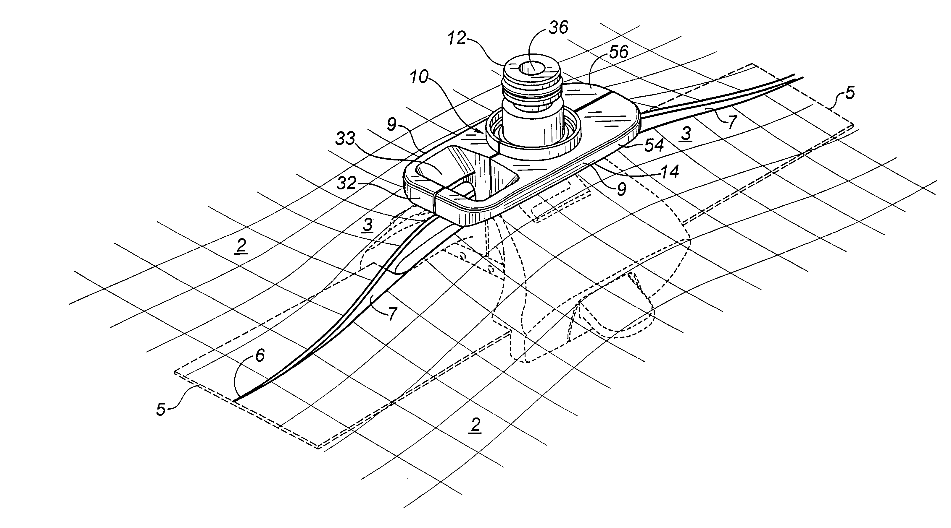
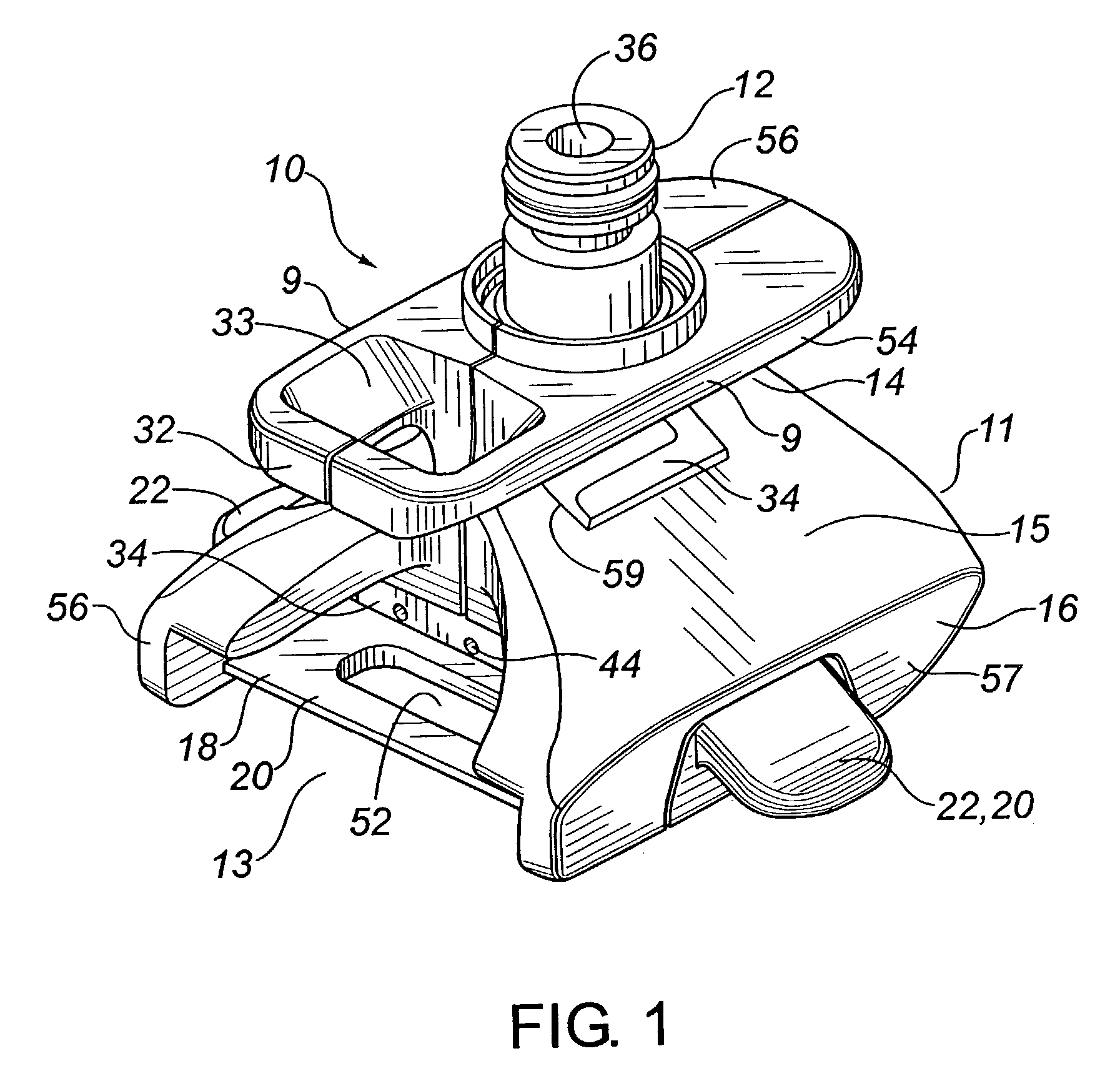
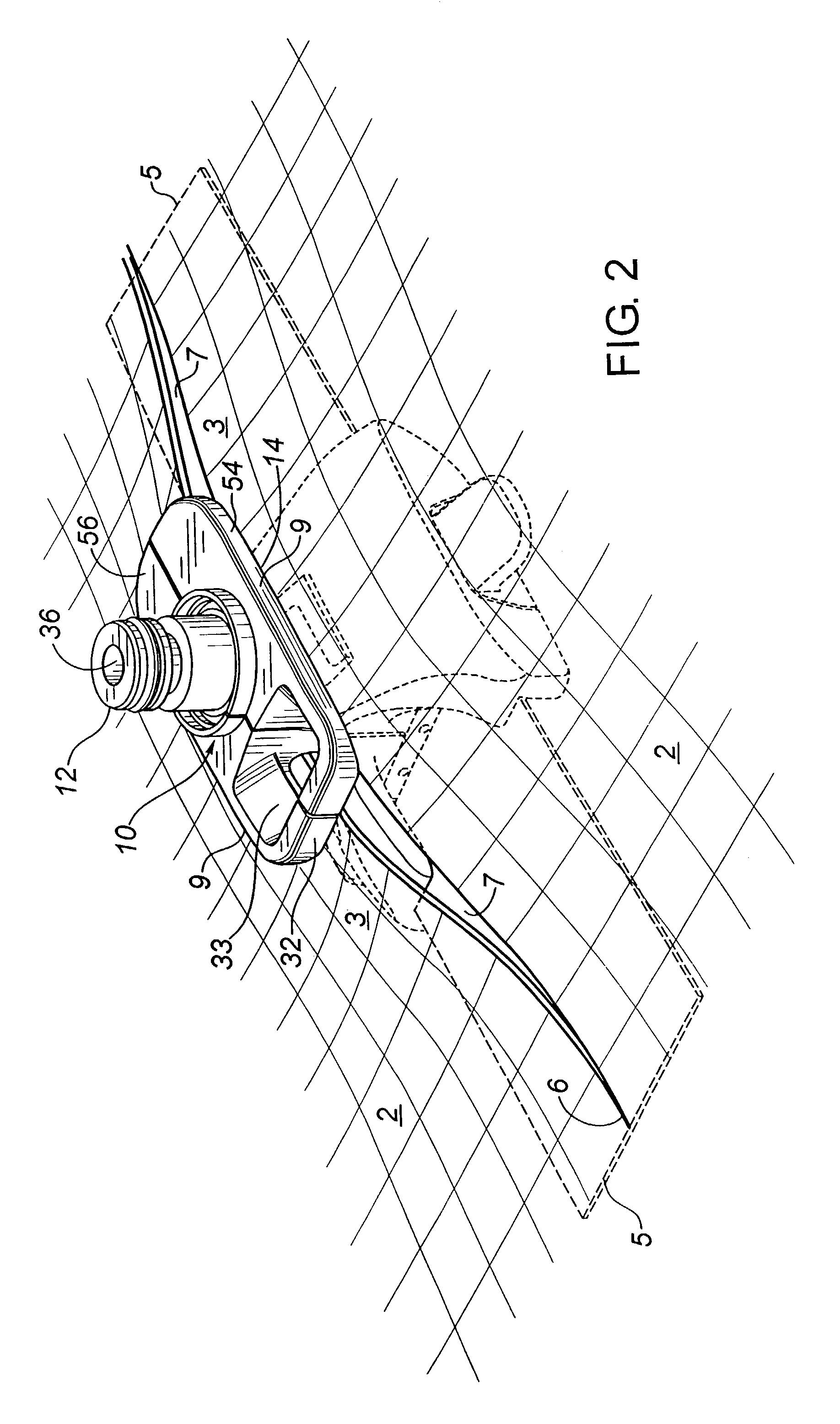
[0052]The apparatus of the present invention is concerned with an application tip for seaming adjacent, side-by-side abutting layers of floor covering and is shown in FIGS. 1, 3, 4, 5 and 6. The apparatus is applicator 10 which comprises, from top to bottom, leg portion 12, ankle portion 14, foot portion 16 and tape retainer portion 18. Applicator 10 has a front leading edge 11 and a rear or trailing edge 13 when in use.

[0053]In the preferred embodiment, as shown in FIGS. 7 and 8, applicator 10 is an assembly of insert 34, right body half 54 and left body half 56. Insert 34 is sandwiched between right body half 54 and left body half 56. Screws 60 pass through holes 58 to fasten right body half 54 and left body half 56 together. When insert 34 is assembled with body halves 54 and 56 to form applicator 10, side surfaces 37 of insert 34 protrude through opening 51 on right body half 54 and through opening 59 on left body half 56. Insert 34 is preferably made of aluminum but may be made...


PUM

PropertyMeasurementUnit
adhesiveaaaaaaaaaa
widthaaaaaaaaaa
lengthaaaaaaaaaa

Abstract

The present invention is concerned with a method and apparatus for seaming together abutting side-by-side layers of planar material with adhesive and a backing tape to form a finished seam extending along the line of abutment. The method consists of laying a backing tape underneath the line of abutment between adjacent layers of planar material, such as floorcovering, followed by dispensing an adhesive along the edges of the abutting layers while simultaneously centering the backing tape with the line of abutment and dispensing adhesive on top of the backing tape. The edges of the abutting layers are then pressed together and against the backing tape until the adhesive has at least partially set thereby forming a finished seam. The apparatus is an applicator tip comprising an upright body having a tape retaining portion for centering the backing tape, a foot portion having wedges for upraising and tilting marginal portions of the abutting layers, an ankle portion that is relatively narrow, and an upper leg portion adapted to connect with an adhesive dispenser via a swiveling elbow connection. A flow passageway extends through the elbow connection from the dispenser to a leg passageway extending from the upper leg portion, through the ankle portion, to the foot portion. The leg passageway connects with an ankle passageway that terminates in orifices on either side of the ankle portion, and with a foot passageway that terminates in orifices on the rear face of the applicator tip. Thus, adhesive injected into the applicator tip by the dispenser is discharged through the orifices on the ankle portion onto the edges of the abutting layers and is discharged through the orifices on the rear face of the foot portion onto the top surface of the backing tape as the applicator is advanced along the line of abutment between the abutting layers.

Description

FIELD OF THE INVENTION[0001]The present invention is concerned with a method and apparatus for seaming abutting side-by-side layers of planar material with adhesive and a backing tape to form a finished seam extending along the line of abutment.Definitions:[0002]For purposes of this specification, “planar material” is intended to include floorcoverings such as carpet and resilient flooring material. “Carpet” refers to a heavy fabric floorcovering made of natural or synthetic textiles that has a woven backing comprised of jute or similarly sturdy fibers. “Resilient flooring” is generally known to include linoleum, rigid-backed vinyl (such as CORLON®), cushion-backed vinyl and homogeneous vinyl. “Sub-floor” refers to the floor surface underneath the floorcovering being installed. “Pad” refers to the layer of underlay that is sometimes installed on the sub-floor prior to the installation of carpet so to provide an additional layer of cushioning. “Open seam” is intended to describe the ...

Claims


Application Information

Patent Timeline
Patent Type & Authority Patents(United States)
IPC IPC(8): B67D5/00B05C3/00B05C3/20B67D5/06B67D99/00A47G27/04B67D7/06E04F21/22
CPCA47G27/0487E04F21/22Y10T156/1717Y10T156/1798Y10T156/172
Inventor DESPINS, MAURICEDESPINS, DAVID
Owner BENO J GUNDLACH
Why Eureka
Try Eureka