Method of jointing and running expandable tubulars

Inactive Publication Date: 2006-02-14
WEATHERFORD TECH HLDG LLC
View PDF44 Cites 43 Cited by
  • Summary
  • Abstract
  • Description
  • Claims
  • Application Information

AI Technical Summary

Benefits of technology

[0016]In another embodiment of the present invention, the connection consists of intermingling conventional threaded connectors with at least one circumferential ring profile.

Problems solved by technology

This method of connecting tubulars, though a reliable means of connecting non-expanding tubulars, is proving to be problematic when these tubulars are expanded.
In the plain wall section of the tubular this process will normally take place in a relatively controlled and uniform way, however, at the point of a threaded connection the changes in wall section which are required in order to form the thread will introduce a very complex and non-uniform stress and deformation during and after expansion, which will significantly change the thread form and compromis

Method used


Image

  • Method of jointing and running expandable tubulars
  • Method of jointing and running expandable tubulars
  • Method of jointing and running expandable tubulars

Examples


Example

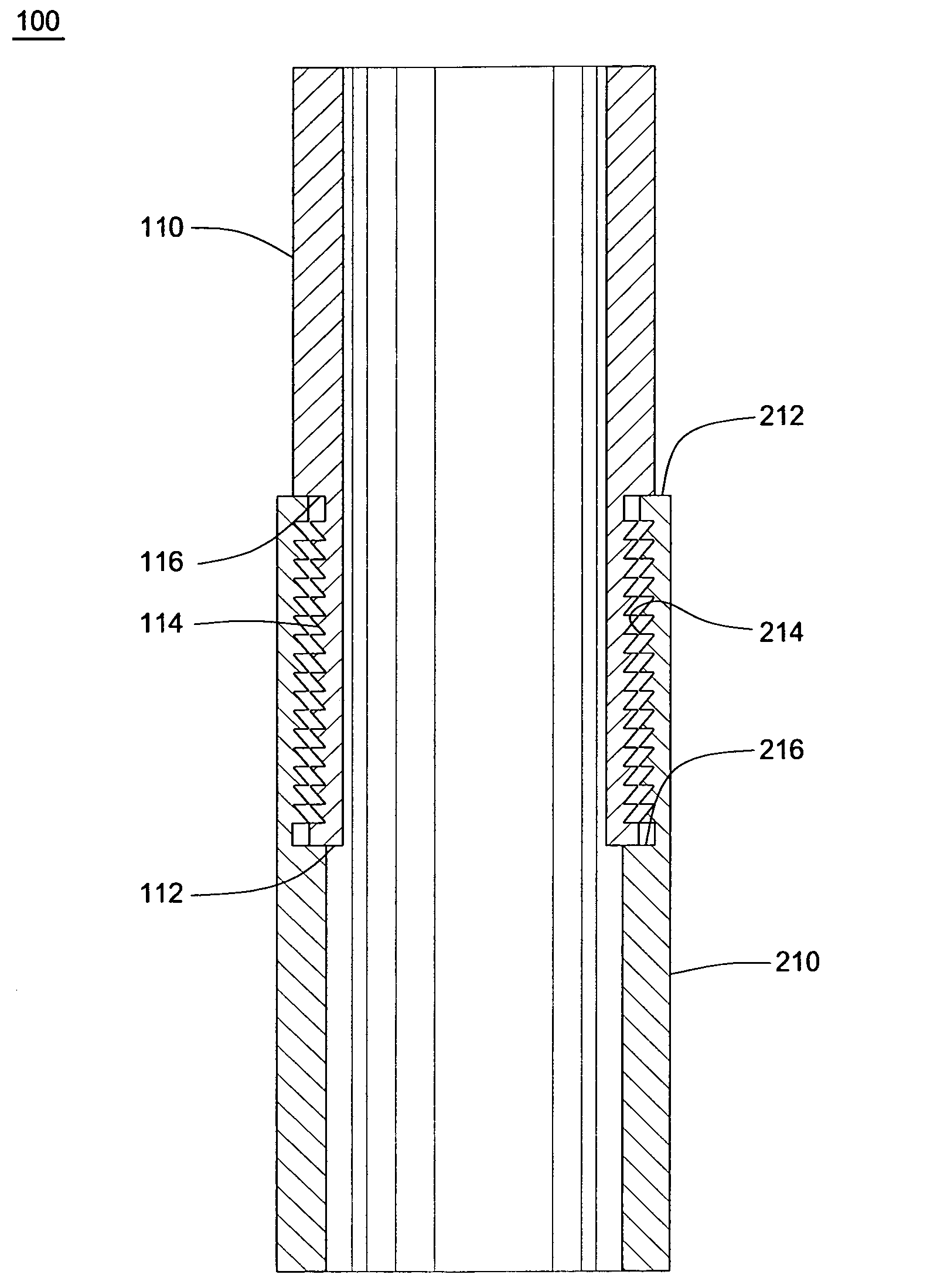
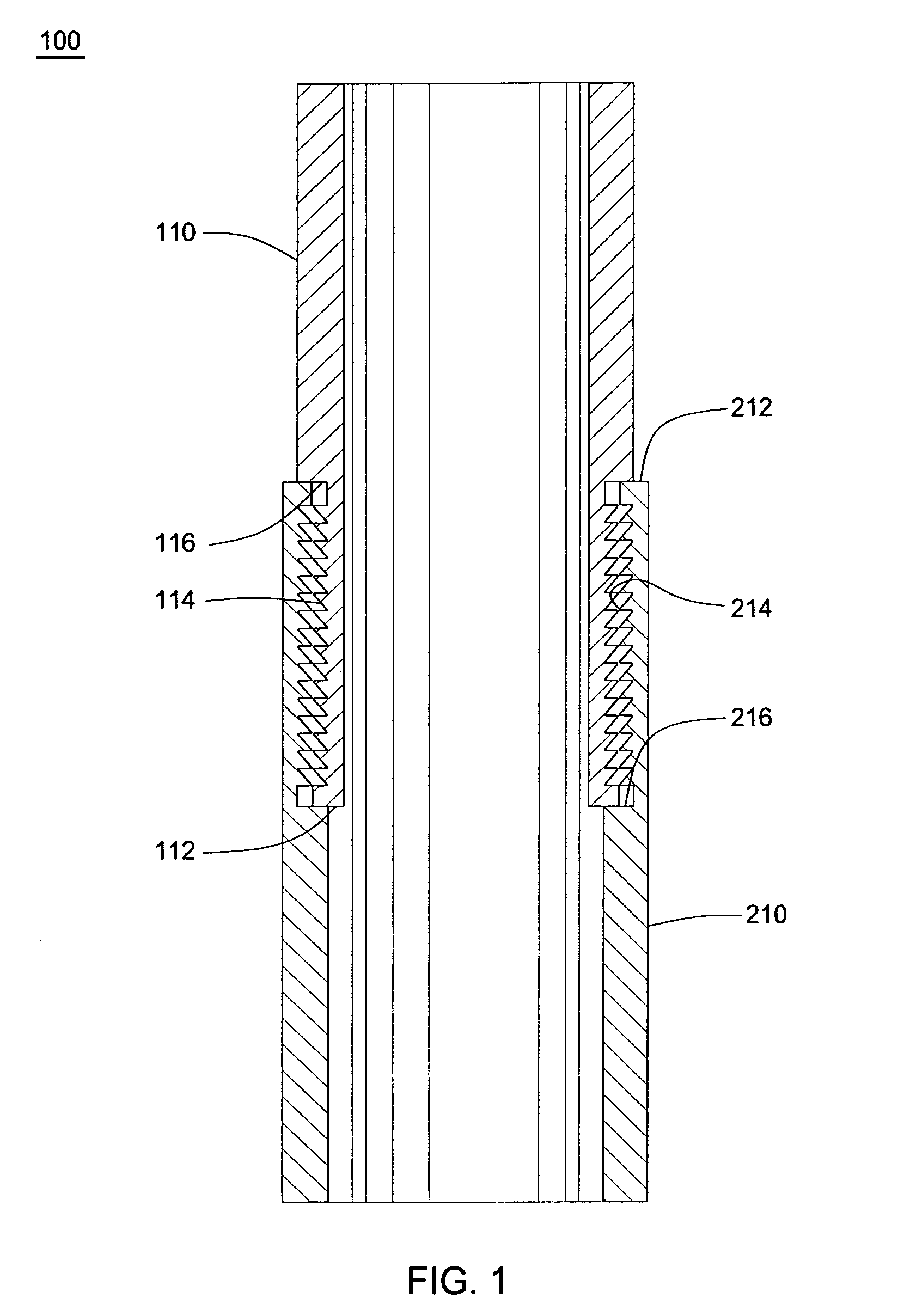
[0029]FIG. 1 is a cross-sectional view of a connector 100 of the present invention. As seen, the connector 100 first comprises a first tubular 110 having an end 112. Disposed on the end of the first tubular 110 are external circumferential ring profiles 114. Also disposed on the end 112 of the first tubular 110 distal to the circumferential ring profiles 114 is a mating shoulder 116.

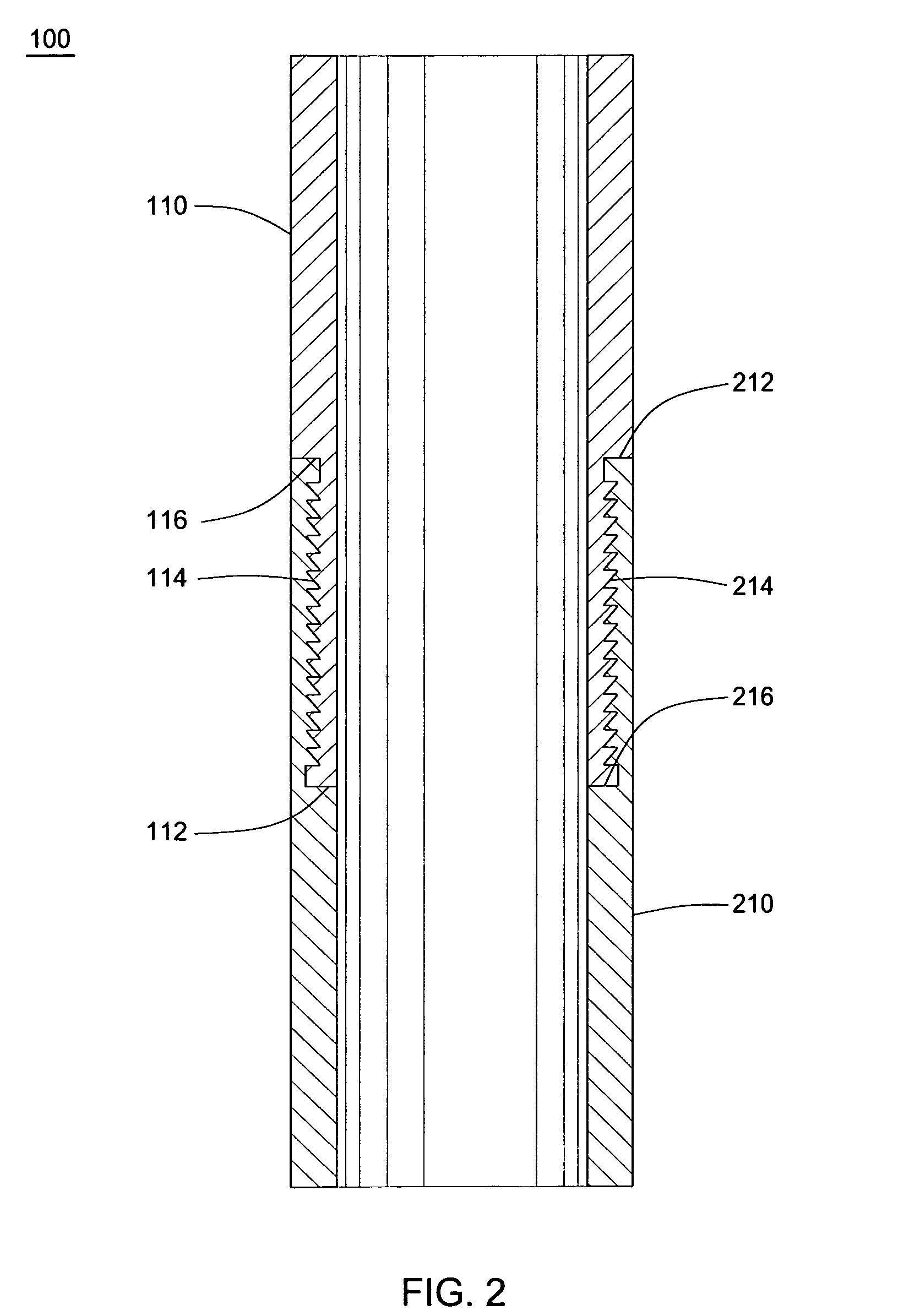
[0030]The connector 100 also comprises a second tubular 210 having an end 212. Disposed on the end of the second tubular 210 is a corresponding number of matching internal circumferential ring profiles 214. The tubulars are to be joined by either expanding the ring profiles 114 of the first tubular 110 into the ring profiles 214 of the second tubular 210, or by compressing the ring profiles 214 of the second tubular 210 around the ring profiles 114 of the first tubular 110, or a combination thereof. Resulting from the expansion or compression of the connection is that the ring profiles 114, 214 will mate...


PUM


Abstract

A connector arrangement used for connecting a first tubular to a second tubular. The first tubular member has at least one circumferential ring profile, and the second tubular member has a corresponding number of matching circumferential ring profiles. When the ring profiles of the two tubulars are mated and interlocked, they form separate and independent fluid seals as well as a mechanical lock able to hold the tubulars together during future expansion of the entire tubular and joint. Further, selecting properties of the tubulars such as yield strength and modulus of elasticity or constraining a diameter of one of the tubulars during expansion or compression forms a tight connection due to elastic recovery of the tubulars.

Description

BACKGROUND OF THE INVENTION[0001]1. Field of the Invention[0002]The present invention generally relates to tubular connectors. In particular, the present invention relates to a method of connecting tubulars in such a way that the connection is prevented from becoming unmade in response to expansion of the tubulars. More particularly, the present invention provides a tubular connection wherein there is at least one concentric interlocking ring profile.[0003]2. Description of the Related Art[0004]In order to access hydrocarbons in subsurface formations, it is typically necessary to drill a bore into the earth. The process of drilling a borehole and of subsequently completing the borehole in order to form a wellbore requires the use of various tubular strings. These tubulars are typically run downhole where the mechanical and seal integrity of the jointed connections are critically important both in the original make-up of the tubulars and during expansion of the tubulars.[0005]Typical...

Claims


Application Information

Patent Timeline
IPC IPC(8): E21B17/043E21B29/10E21B43/10F16L25/10E21B17/04E21B17/08E21B19/16F16L13/14F16L13/16
CPCE21B17/04E21B17/08E21B19/16F16L13/168E21B43/105E21B43/106F16L13/147E21B43/103E21B17/02
Inventor SIMPSON, NEIL A. A.PLUCHECK, CLAYTONCOON, ROBERT J.
Owner WEATHERFORD TECH HLDG LLC
Why Eureka
Try Eureka