Conveyor belt modules with embedded rollers retained in the modules and associated method

a technology of conveyor belts and modules, applied in the direction of conveyor parts, rollers, transportation and packaging, etc., can solve the problems of reducing the pull strength of the belt, and affecting the service life of the bel

Active Publication Date: 2006-02-14
LAITRAM LLC
View PDF15 Cites 46 Cited by
  • Summary
  • Abstract
  • Description
  • Claims
  • Application Information

AI Technical Summary

Problems solved by technology

Because belt tension is borne by the hinge eyes, removing a few decreases the pull strength of the belt.
As another example, snap-in roller assemblies can break.
If the snap-in retention structure is broken, the broken pieces or the assembly itself can disengage from the belt and contaminate product or cause other damage.
This makes for an expensive mold and decreases the duty cycle of the mold machine.

Method used


Image

  • Conveyor belt modules with embedded rollers retained in the modules and associated method
  • Conveyor belt modules with embedded rollers retained in the modules and associated method
  • Conveyor belt modules with embedded rollers retained in the modules and associated method

Examples


Embodiment Construction

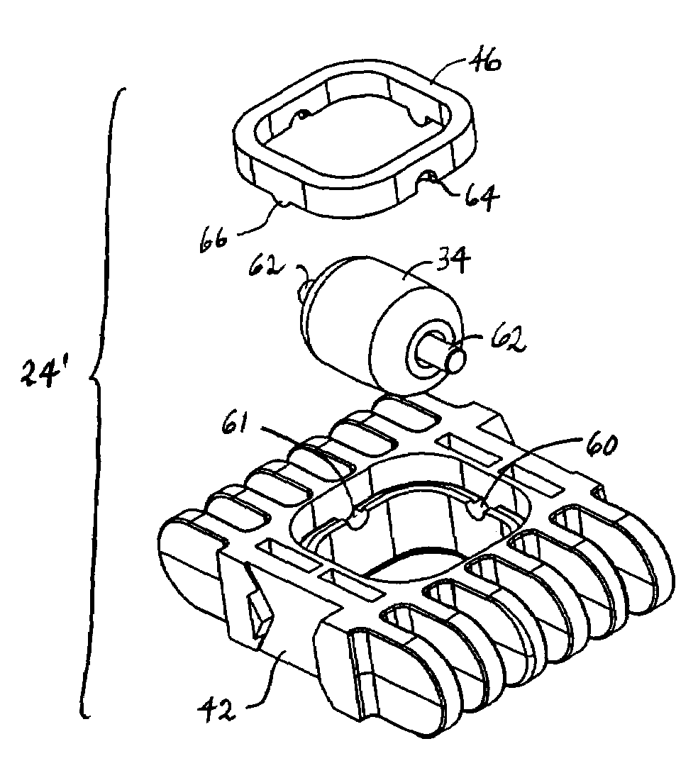
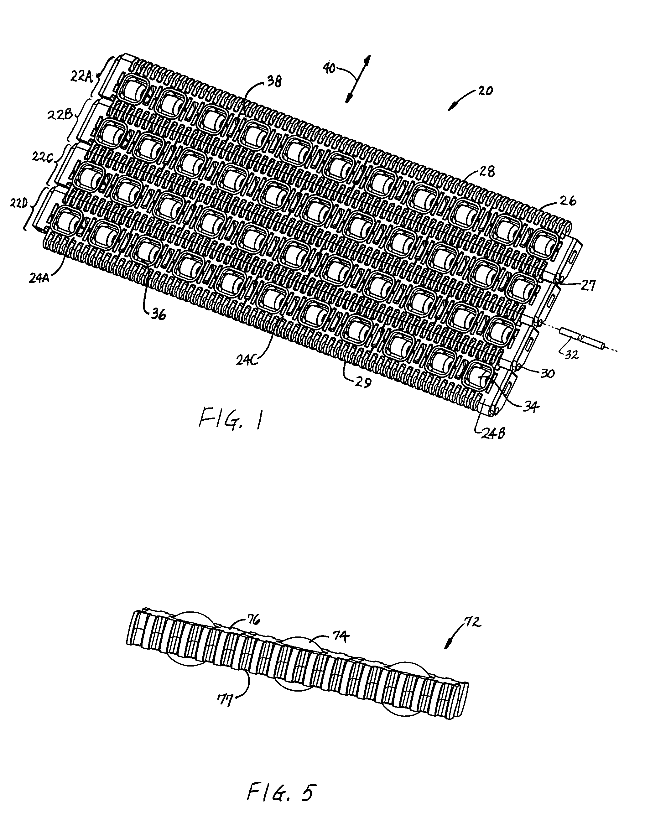
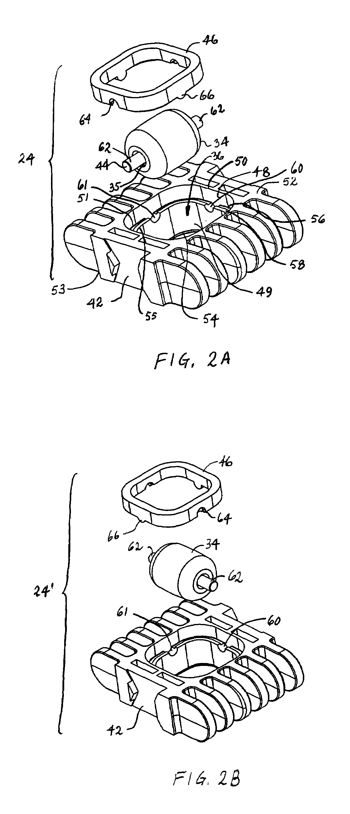
[0022]A portion of a modular plastic conveyor belt having modules embodying features of the invention is shown in FIG. 1. The belt 20 is constructed of a series of rows 22A–D of belt modules 24: short edge modules 24A, long edge modules 24B, and interior modules 24C. Although the modules are preferably arranged in a bricklay, the belt could be formed otherwise, such as with a single module per row. Each module extends longitudinally from a first end 26 to a second end 27. A first set of hinge eyes 28 is arranged with the hinge eyes spaced apart along the first end, and a second set of hinge eyes 29 is arranged with the hinge eyes spaced apart along the second end. The first set of hinge eyes of one row of modules interleaves with the second set of hinge eyes of an adjacent row. Aligned apertures 30 in the interleaved hinge eyes form a transverse passageway across the width of the belt. A hinge rod 32 journaled in the passageway connects consecutive rows together in a hinge joint tha...


PUM


Abstract

A plastic conveyor belt module with embedded rollers retained in the module and a method for making such a module. The module includes a module body forming a cavity, a roller in the cavity, and a retainer received in the cavity to hold the roller rotatably in place. A salient portion of the roller extends outward from the cavity through the retainer past an outer surface of the module. The retainer is attached to the module body by ultrasonic welding, epoxy- or solvent-bonding, spin welding, electromagnetic welding, staking, screwing, or locking.

Description

BACKGROUND OF INVENTION[0001]This invention relates to power-driven conveyors generally and, more specifically, to modular plastic conveyor belts with embedded rollers and methods for retaining the rollers.[0002]Modular plastic conveyor belts are widely used to convey a variety of articles. Rollers are often installed in the belts for product accumulation, singulation, sortation, indexing, or side off-transfer. Rollers are also used to lower the friction between belts and conveyor supporting wearstrips or side rails. One way rollers are integrated into conveyor belts is by mounting them for rotation on a hinge rod interconnecting successive rows of belt modules. Another way is snapping roller assemblies onto belt modules. Yet another way is molding rollers into belt modules when the modules are being formed. But each of these methods has its shortcomings.[0003]For example, mounting rollers on hinge rods typically requires that hinge eyes be removed first to make room for the rollers...

Claims


Application Information

Patent Timeline
Patent Type & Authority Patents(United States)
IPC IPC(8): B65G17/00B65G17/08B65G17/32B65G39/20
CPCB65G17/08B65G39/20B65G17/32
Inventor SOFRANEC, RICHARD J.RAU, BRIEN G.
Owner LAITRAM LLC
Why Eureka
Try Eureka