

Headlamp mounting structure for automobile
a technology for mounting structures and headlamps, which is applied in the direction of lighting elements, transportation and packaging, lighting and heating equipment, etc., can solve the problems of poor operability, deterioration of uneven gap or step between the parting portion between the headlamp unit and the front end of the front fender, etc., to achieve the effect of simplifying the mounting operation and maintaining the precision of the mounting position
- Summary
- Abstract
- Description
- Claims
- Application Information
AI Technical Summary
Benefits of technology
Problems solved by technology
Method used
Image

Examples
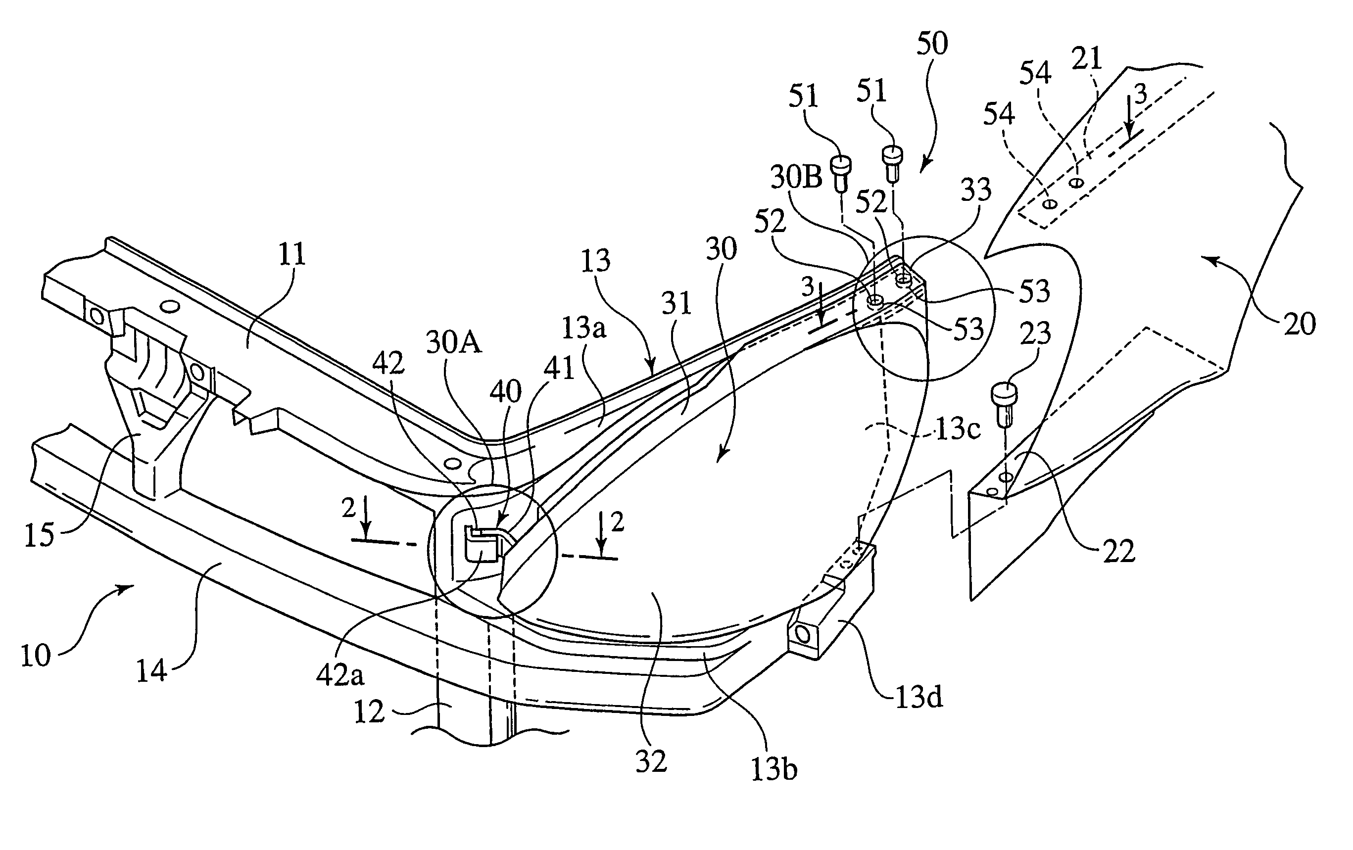
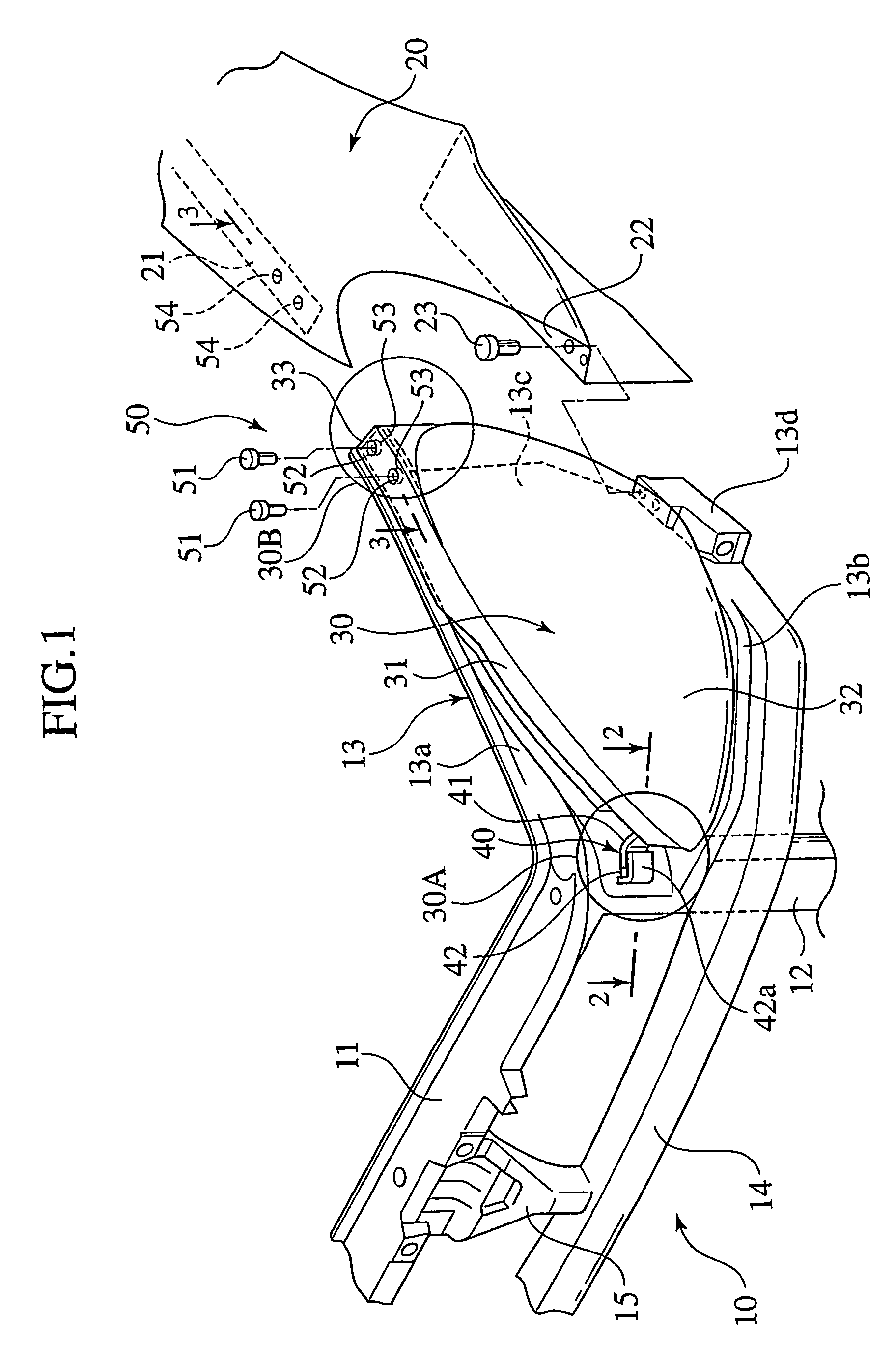
first embodiment
[0040]In this first embodiment, the front mounting position 30A is of an inserting structure 40, and the rear mounting position 30B is of a fastening structure 50.
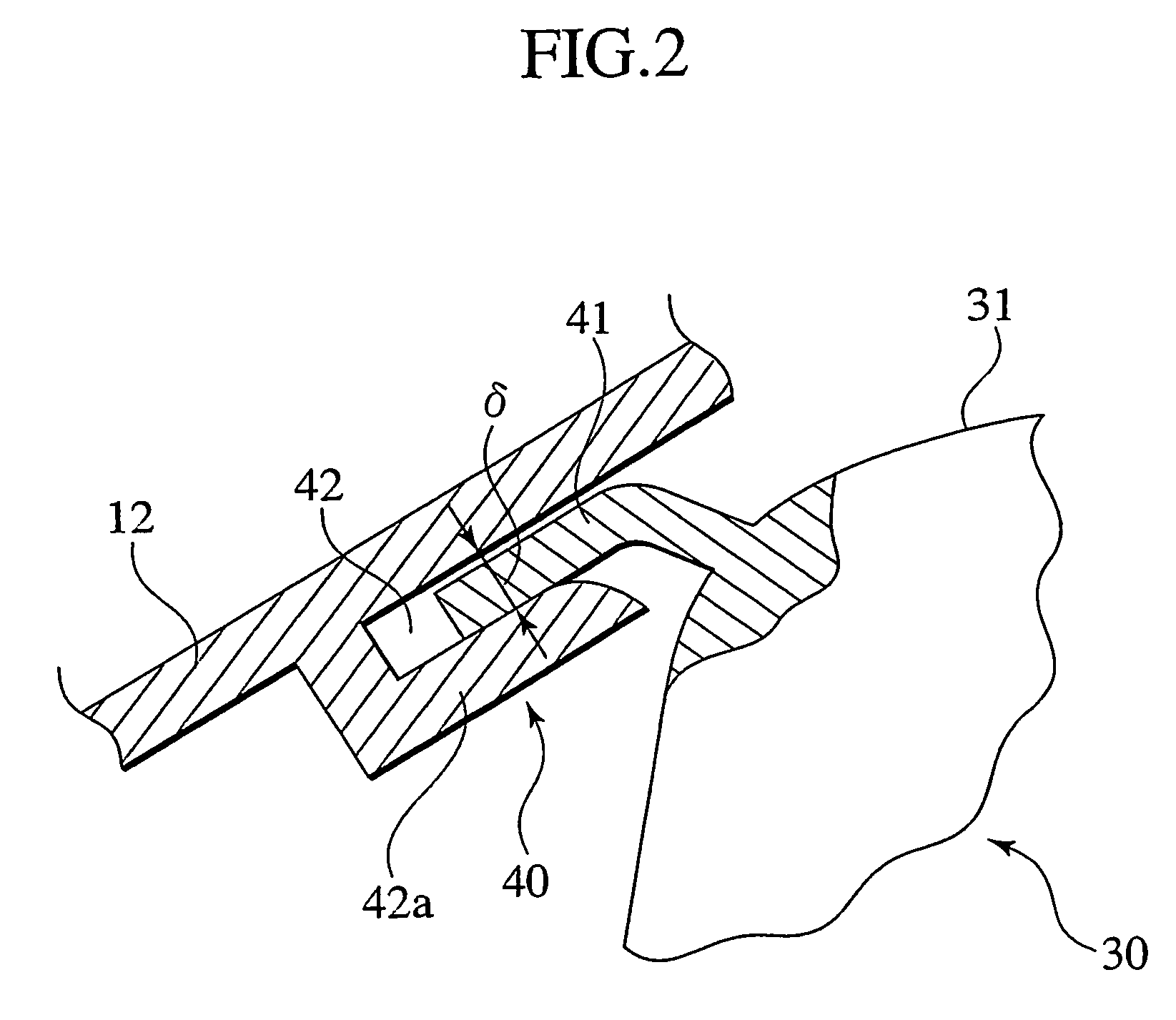
[0041]As shown in FIG. 2, the inserting structure 40 comprises a flange portion 41 as an inserting portion projecting from the housing 31 of the headlamp unit 30 along a mounting direction of the headlamp unit 30, and a receiving portion 42 which is provided on an outer surface of the pillar 12 and into which the flange portion 41 is fitted.
[0042]The flange portion 41 projects such as to incline from a front end of the housing 31 forward of the vehicle and inward along the mounting direction of the headlamp unit 30. The receiving portion 42 has an L-shaped projection 42a projecting from a side surface of the pillar 12. A gap δ substantially corresponding to a thickness of the flange portion 41 is formed between the side portion 13 and the L-shaped projection 42a. The flange portion 41 is tightly inserted into the gap δ, an...
second embodiment
[0060]In the case of the second embodiment, if the annular projection 52c is crushed, the annular projection 52c is reduced in diameter in a direction of the center as shown in the enlarged sectional view of FIG. 6 so that the annular projection 52c is brought into contact with a bolt shaft portion under pressure. Therefore, the headlamp unit 30 slides and moves within the margin having the same diameter as that of the bolt-inserting hole 52, the automatic alignment is carried out, and the same effect as that described above can be obtained.
third embodiment
[0061]FIG. 7 to FIG. 9 show a third embodiment, the same constituent portions as those of the previous embodiment are designated with the same symbols, and redundant explanation is omitted.
[0062]FIG. 7 is an exploded perspective view showing a headlamp mounting portion on one side of a front portion of a car body. FIG. 8 is an enlarged sectional view of a front side mounting position taken along a line 8—8 in FIG. 7. FIG. 9 is an enlarged sectional view of an assembled state of a rear side mounting position taken along a line 9—9 in FIG. 7.
[0063]According to the headlamp mounting structure of the third embodiment, the front mounting position 30A is a fastening structure 60, and the rear mounting position 30B is an inserting structure 40a.
[0064]As shown in FIG. 8, in the fastening structure 60 of the front mounting position 30A, a thick projection 34 projecting from a front end of the housing 31 of the headlamp unit 30 and a side portion of the pillar 12 of the radiator core support...
PUM
 Abstract
Description
Claims
Application Information