
Roller bearing

Inactive Publication Date: 2006-02-14
NSK LTD
View PDF9 Cites 15 Cited by
  • Summary
  • Abstract
  • Description
  • Claims
  • Application Information

AI Technical Summary

Benefits of technology

[0007]This invention has been achieved in the light of the above-mentioned problems, and it is an object of the invention to provide a roller bearing that is prevent from an increased cost, seizure or edge load and a premature wear due to skew.

Problems solved by technology

However, if the cylindrical roller is rolling while the rolling contact surfaces of rolling elements of the inner ring and the outer ring are skewed, an edge part of the cylindrical roller contacts the inner side face of the flange portion, causing a shorter life of the bearing.
However, when the cylindrical roller is not skewed, an end face of the cylindrical roller contacts a grinding clearance groove of the inner ring and / or the outer ring, producing an edge load to cause a premature wear, when subjected to a thrust load.
Therefore, the roller bearing as described in JP-A-2002-70874 is required to manufacture by setting up the opening angle of the inner side face of flange portion strictly to keep the contact position between cylindrical roller and flange portion invariable, causing the increased cost.
Since the roller bearing as described in JP-A-2002-70874 has a narrower clearance formed between the end face of cylindrical roller and the inner side face of flange portion with the contact position between the cylindrical roller and the flange portion therebetween, the lubricant such as grease is difficult to permeate, resulting in a problem that seizure is more likely to occur.

Method used


Image

  • Roller bearing
  • Roller bearing
  • Roller bearing

Examples


Embodiment Construction

[0024]Referring to FIGS. 1 to 10, the preferred embodiments of the present invention will be described below.

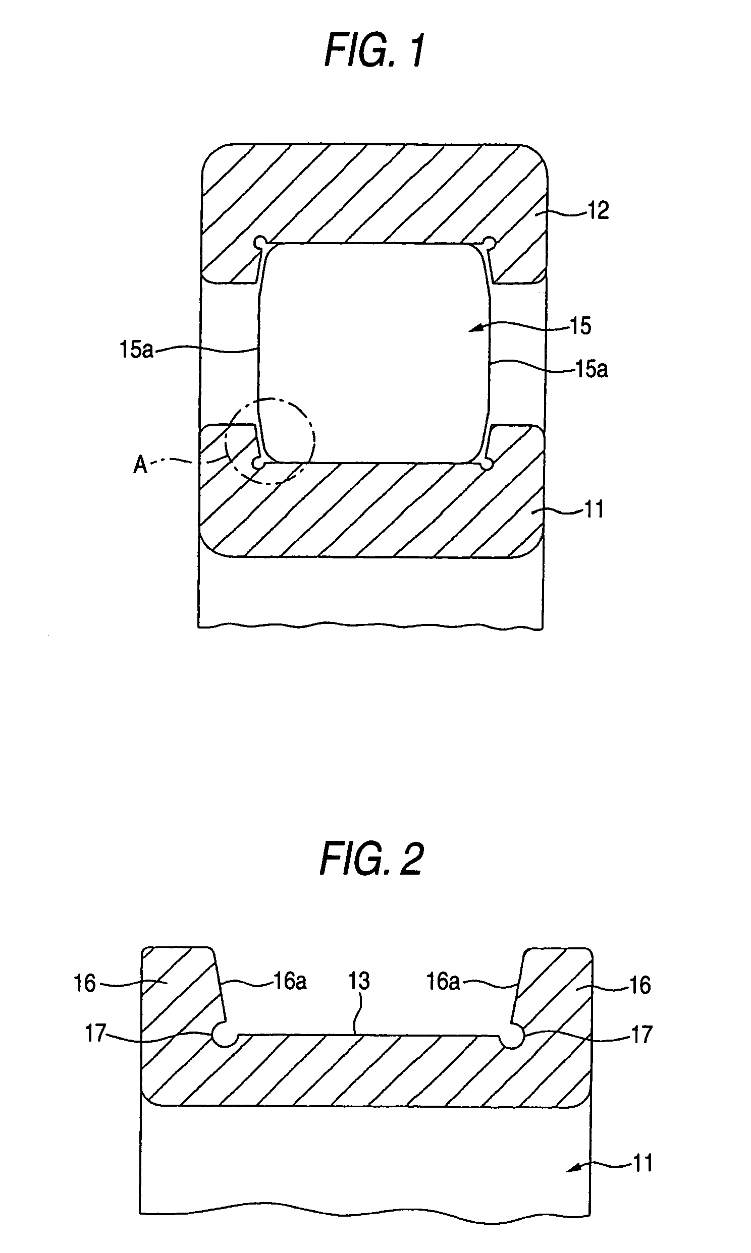
[0025]FIG. 1 is an axial cross-sectional view of a roller bearing according to one embodiment of the invention. The roller bearing according to this embodiment of the invention comprises an inner ring 11 and an outer ring 12, as shown in FIG. 1.

[0026]The outside diameter of the inner ring 11 is smaller than the inside diameter of the outer ring 12. The inner ring 11 is formed like an annulus ring. A rolling contact surface 13 of rolling element is formed on an outer circumferential face of the inner ring 11, as shown in FIG. 2. On the other hand, the inside diameter of the outer ring 12 is larger than the outside diameter of the inner ring 11. The outer ring 12 is formed like an annulus ring. A rolling contact surface 14 of rolling element is formed on an inner circumferential face of the outer ring 12, as shown in FIG. 3. These rolling contact surfaces 13 and 14 of rolling e...


PUM


Abstract

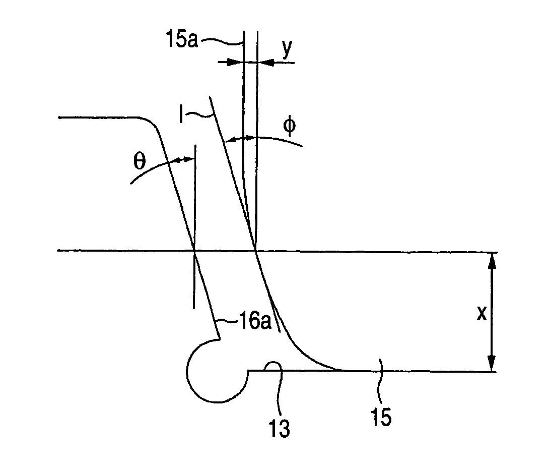
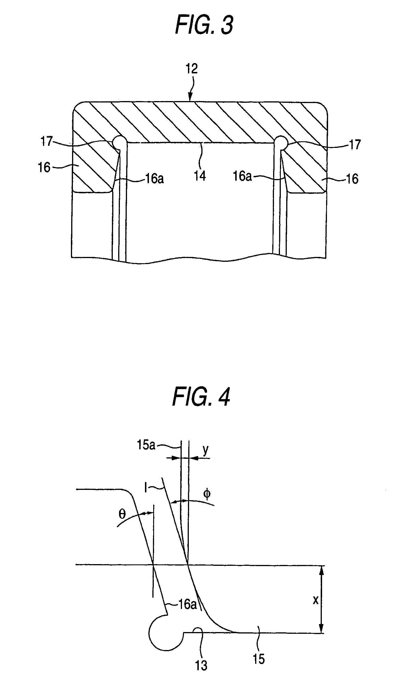
A roller bearing includes an inner ring, an outer ring, a plurality of cylindrical rollers each provided between rolling contact surfaces of the inner ring and the outer ring. Each of the cylindrical rollers includes an end face having a peripheral part that is crowned. A flange portion is formed at an outer circumferential face end part of the inner ring and / or an inner circumferential face end part of the outer ring. The peripheral part is crowned in a curving shape represented by an exponential function of y=a·exp(−b·x); where a and b are constants, x is a distance from the rolling contact surface in a radial direction of the cylindrical roller, and y is a crowning fall-off amount from a central part of the end face of the cylindrical roller in an axial direction of the cylindrical roller.

Description

BACKGROUND OF THE INVENTION[0001]1. Field of the Invention[0002]The present invention relates to improvements in a roller bearing using cylindrical rollers as rolling elements.[0003]2. Background Art[0004]A roller bearing using cylindrical rollers as rolling elements has often a thrust load, as well as a radial load, and has a structure in which a flange portion is provided on an outer circumferential face end part of an inner ring and an inner circumferential face end part of an outer ring, and an end face of a cylindrical roller is contacted with an inner side face of the flange portion to receive the thrust load. However, if the cylindrical roller is rolling while the rolling contact surfaces of rolling elements of the inner ring and the outer ring are skewed, an edge part of the cylindrical roller contacts the inner side face of the flange portion, causing a shorter life of the bearing. For this reason, the inner side face of the flange portion is inclined at a predetermined ope...

Claims


Application Information

Patent Timeline
IPC IPC(8): F16C33/34F16C19/26F16C33/36F16C33/58
CPCF16C19/225F16C19/26F16C33/34F16C2240/50F16C2240/40F16C33/585F16C2240/34
Inventor IDE, YOSHIROICHIMARU, MASATAKEOOURA, YUKIOKAMAMURA, YUKO
Owner NSK LTD
Learn More