Plasma display panel manufacturing apparatus and manufacturing method

a technology of display panel and manufacturing method, which is applied in the direction of gas exhaustion means, identification means, instruments, etc., can solve the problems of low productivity, insufficient exhaustion, and poor purity of luminescent gas

Inactive Publication Date: 2006-02-14
PANASONIC CORP
View PDF20 Cites 8 Cited by
  • Summary
  • Abstract
  • Description
  • Claims
  • Application Information

AI Technical Summary

Benefits of technology

[0022]A method for manufacturing a plasma display panel according to the present invention is a method for manufacturing a plasma display panel formed by heating a low-melting-point glass so as to join a front substrate to a rear substrate, after which a luminescent gas is introduced into the plasma display panel via a gas introduction port provided in either the front substrate or the rear substrate, after which the gas introduction port is sealed, the method comprising: a first step of fixing the front substrate of said plasma display panel to the rear substrates, placing the substrates into a joining chamber, and then performing vacuum exhausting an inside of the joining chamber, a second step of heating a sealing glass provided on the front substrate or the rear substrate, so as to join the front substrate to the rear substrate, a third step of placing the joined plasma display panel in a gas introduction and sealing chamber which has been vacuum-exhausted, and then vacuum exhausting an inside of the plasma display panel, a fourth step of making an inside of the gas introduction and sealing chamber an atmospheric pressure, a fifth step of introducing the luminescent gas into the plasma display panel which has been vacuum-exhausted, and a sixth step of sealing the gas introduction port of the plasma display panel.
[0023]In a second aspect of a manufacturing method according to the present invention, the sixth step comprising: a step of supplying a cover member formed by a metal sheet to which a low-melting-point glass is applied to a first location within the gas introduction and sealing chamber, a step of moving the cover member to a second location which is over a heating apparatus provided within the gas introduction and sealing chamber, and a step of pressing the metal sheet to which is applied a low-melting-point glass on the heating apparatus against the gas introduction port and sealing the gas introduction port.

Problems solved by technology

In the above-noted methods of manufacturing a plasma display panel of the prior art, however, because many minute separators having a height of 100 to 200 μm between the front substrate and the rear substrate are provided, and the conductance of the exhaust tube is small, 10 or more hours is required for vacuum exhausting degassing, making the productivity low.
Additionally, there is insufficient exhausting and poor purity of the luminescent gas depending upon the lot, this manifesting itself as the problem of a tendency toward variation in the discharge characteristics.
Additionally, because the glass tube (chip tube) remaining after the exhaust tube is removed is extremely fragile, and subject to breakage with even a small shock, not only is it necessary to take extreme care when handling the panel, but also when the plasma display panel is combined with a driving electronic circuit to form a module, it is necessary to mount a protective cap, and to establish a design that avoids interference in electronic components and the printed circuit board.
With regard to the second above-noted manufacturing method of the past, in which there is no exhaust tube, although there is a significant improvement in the exhausting time, residual gas is sealed within the panel when sealing is done, thereby leading to a deterioration of the purity of the luminescent gas.
Additionally, amount of costly luminescent gas used is large, causing the problem of high cost.
However, these inventions do not solve above mentioned drawbacks.

Method used


Image

  • Plasma display panel manufacturing apparatus and manufacturing method
  • Plasma display panel manufacturing apparatus and manufacturing method
  • Plasma display panel manufacturing apparatus and manufacturing method

Examples


Embodiment Construction

[0029]Preferred embodiments of an apparatus and a method for manufacturing a plasma display panel are described in detail below, with references made to relevant accompanying drawings.

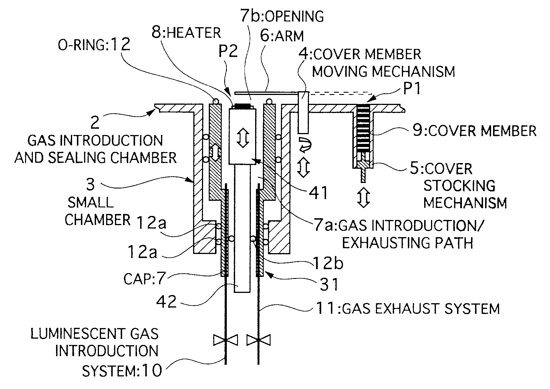
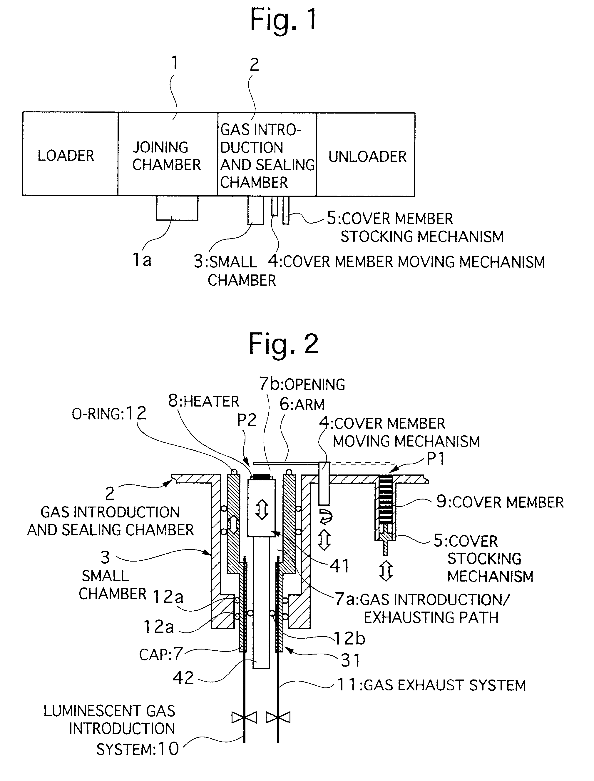
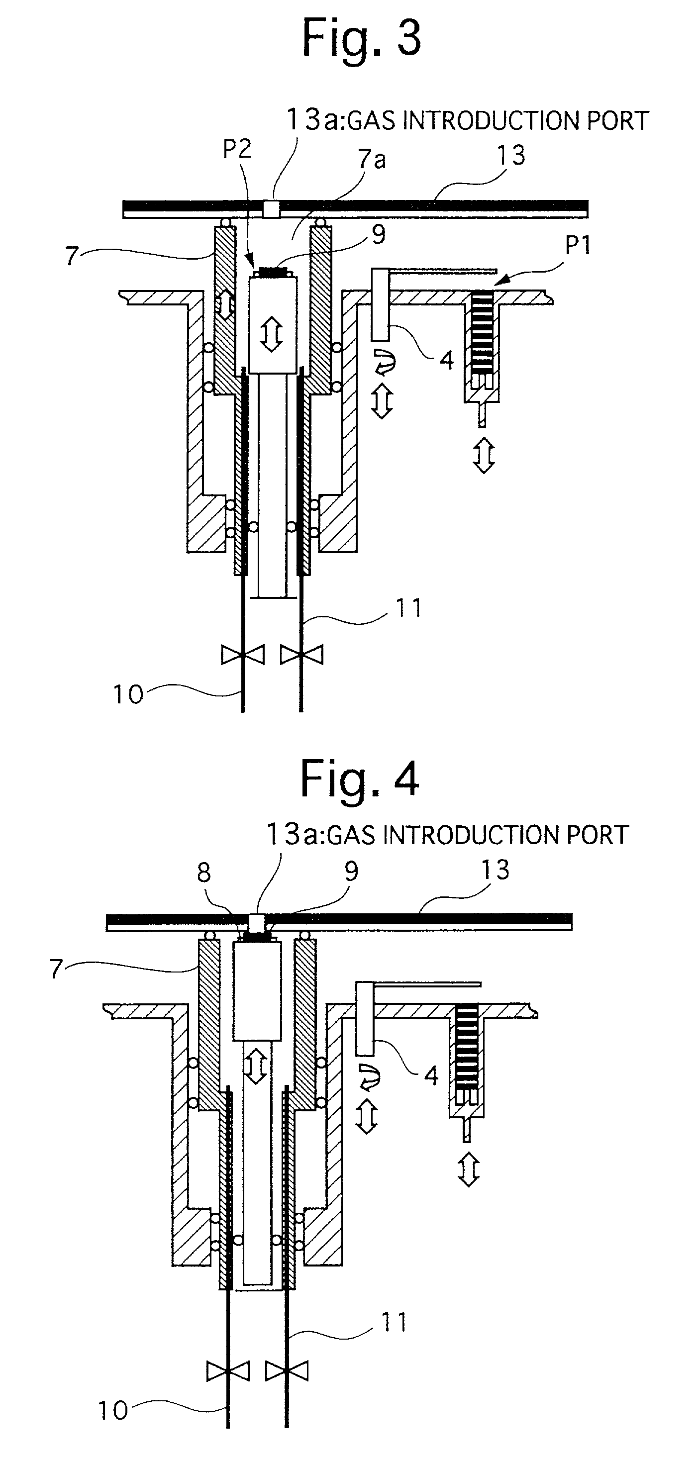
[0030]FIG. 1 to FIG. 5 illustrate an apparatus and a method for manufacturing a plasma display panel according to the present invention, these drawings showing an apparatus for manufacturing a plasma display panel, this apparatus having a joining chamber 1 in which the front and rear substrates are joined by heating a low-melting-point glass, thereby forming the plasma display panel, and a gas introduction and sealing chamber 2, in which a luminescent gas or discharge gas is introduced into the plasma display panel via a gas introduction port 13a provided in the front substrate or the rear substrate, after which the as introduction port is sealed.

[0031]In the gas introduction and sealing chamber 2, there is a first mechanism 5 for supplying a cover member 9 made of a metal sheet to which a low-melting-...


PUM


Abstract

The apparatus for manufacturing a plasma display panel having a first mechanism for supplying a cover member formed by a metal sheet to which low-melting-point glass is applied to a first location within the gas introduction and sealing chamber, a second mechanism provided in the gas introduction and sealing chamber for moving the cover member from the first location to a second location which is over a heating apparatus provided in the gas introduction and sealing chamber, a third mechanism provided in the gas introduction and sealing chamber for performing vacuum exhausting an inside of the plasma display panel and then introducing a luminescent gas into the plasma display panel, and a fourth mechanism provided in the gas introduction and sealing chamber for heating the metal sheet to which the low-melting-point glass is applied by using the heating apparatus, so that the gas introduction port is sealed by the low-melting-point glass.

Description

BACKGROUND OF THE INVENTION[0001]1. Field of the Invention[0002]The present invention relates to a plasma display panel manufacturing apparatus, and to a manufacturing method therefor, and more particularly to an apparatus for performing integrated panel sealing, release of exhaust gas, introduction of luminescent gas or discharge gas, and vacuum sealing, and a method of manufacturing a plasma display panel using this apparatus.[0003]2. Related Art[0004]A plasma display panel is generally formed by a front substrate and a rear substrate which have mutually perpendicular opposing electrodes on each of the substrates, a glass tube (hereinafter referred to as an exhaust tube) mounted by low-melting-point glass so as to join a through hole provided beforehand on the rear substrate for the purpose of introducing and exhausting gas, these elements being placed in a sealing furnace so as to melt the low-melting-point glass and form the glass vessel. In addition to release of the exhaust ga...

Claims


Application Information

Patent Timeline
Patent Type & Authority Patents(United States)
IPC IPC(8): H01J9/38G09F9/00H01J9/385H01J9/26H01J9/395H01J9/40H01J11/46H01J11/48H01J11/54
CPCH01J9/261H01J2209/261H01J9/46H01J9/24H01J9/38H01J11/20
Inventor SAEKI, HIROSHI
Owner PANASONIC CORP
Why Eureka
Try Eureka