Viscous fluid injection system
- Summary
- Abstract
- Description
- Claims
- Application Information
AI Technical Summary
Benefits of technology
Problems solved by technology
Method used
Image
Examples
Embodiment Construction
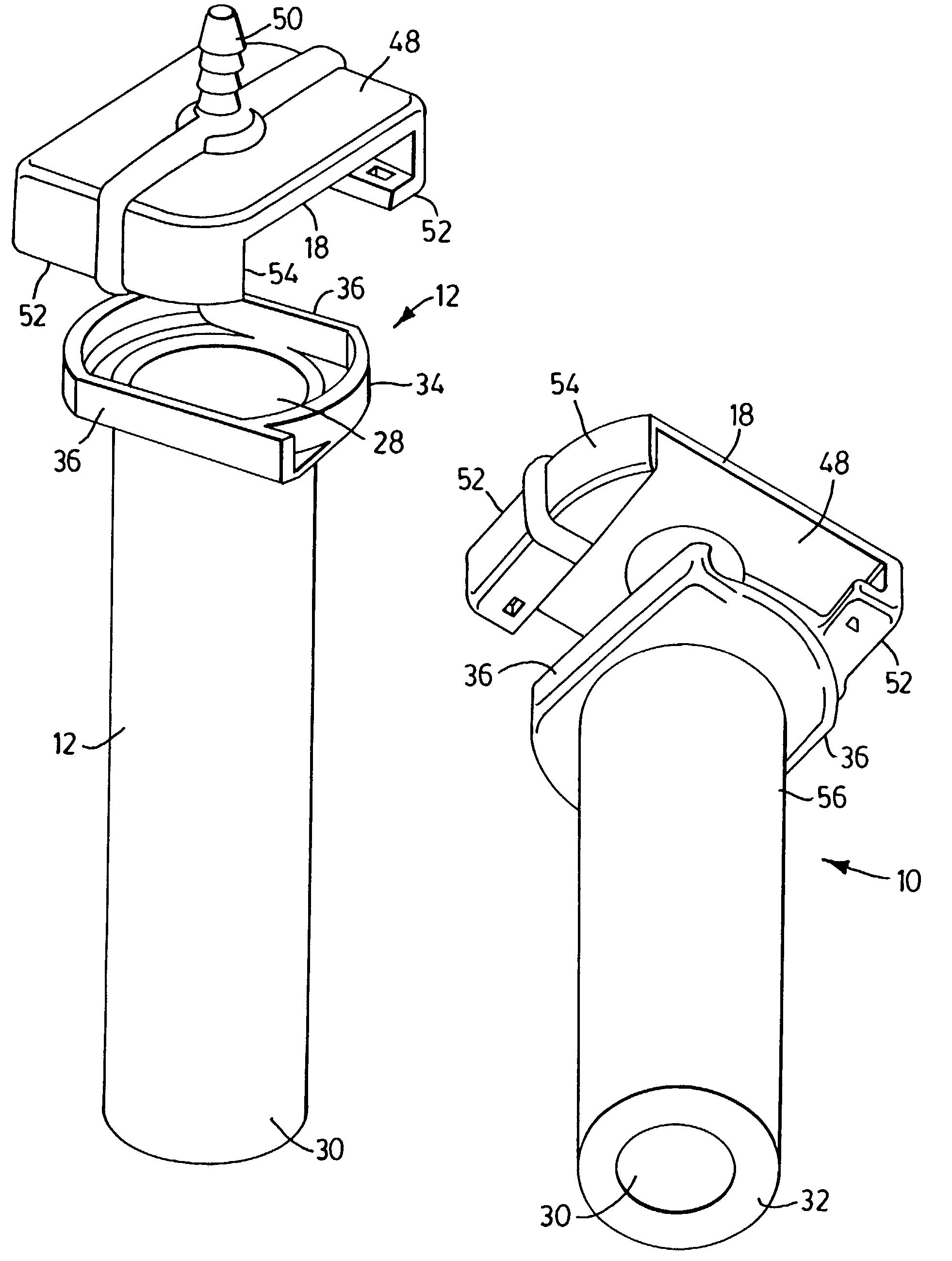
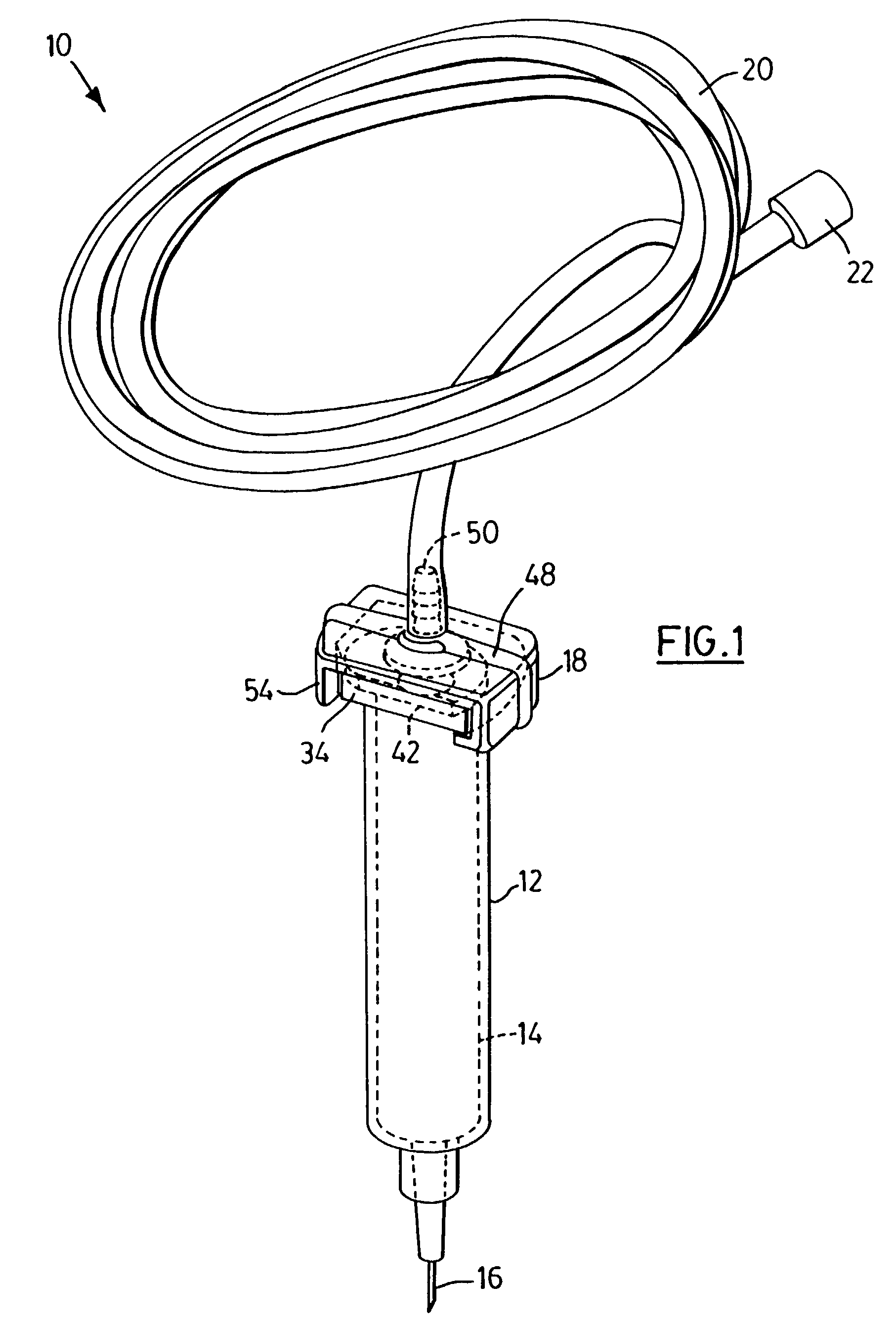
[0027]Referring to FIG. 1, a perspective view of an assembled cylindrical sleeve and locking assembly is shown generally at 10 and includes a cylindrical sleeve 12 with a syringe 14 and associated needle or cannula 16 contained therein and a locking head 18 for locking syringe 14 into sleeve 12. A flexible tube 20 is attached at one end thereof to locking head 18 and the other end has a coupling 22 attached thereto for attachment of tube 20 to a pressurizing controller also known as a viscous fluid injection machine (not shown).
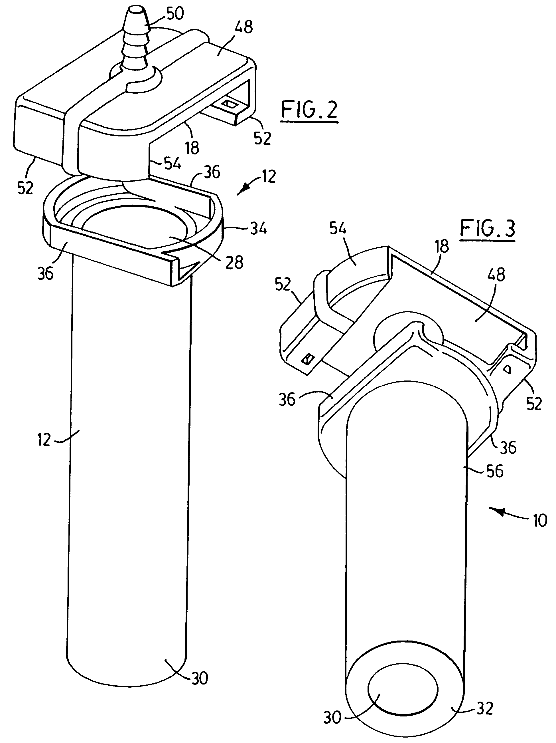
[0028]With particular reference to FIGS. 2, 3 and 4, cylindrical sleeve 12 includes a hole 28 at one end of the cylindrical sleeve 12 large enough to receive syringe 14 (FIG. 1) inserted into sleeve 12 and a smaller hole 30 at the other end of the sleeve 12 defined by a circular inner edge 32 in which the end of the cylindrical body of syringe 14 fits with the needle or cannula 16 (FIG. 1) projecting through hole 30. Sleeve 12 includes an L-shaped flange 34 p...
PUM
 Abstract
Description
Claims
Application Information
 - R&D
- Intellectual Property
- Life Sciences
- Materials
- Tech Scout
- Unparalleled Data Quality
- Higher Quality Content
- 60% Fewer Hallucinations
Browse by: Latest US Patents, China's latest patents, Technical Efficacy Thesaurus, Application Domain, Technology Topic, Popular Technical Reports.
© 2025 PatSnap. All rights reserved.Legal|Privacy policy|Modern Slavery Act Transparency Statement|Sitemap|About US| Contact US: help@patsnap.com


