Process for producing a membrane electrode assembly for fuel cells

a fuel cell and membrane electrode technology, applied in the direction of fuel cells, coatings, electrochemical generators, etc., can solve the problem that the process does not provide complete membrane electrode assemblies, and achieve the effect of improving electrical performan

Inactive Publication Date: 2006-02-14
UMICORE AG & CO KG
View PDF14 Cites 30 Cited by
  • Summary
  • Abstract
  • Description
  • Claims
  • Application Information

AI Technical Summary

Benefits of technology

[0037]With this procedure, it is advantageous if the ink for producing the second catalyst layer contains predominantly water as solvent. This prevents the ink from penetrating into the pore system of the gas distribution layer during the coating process and having a detrimental effect on the performance of the final fuel cell.
[0054]To improve linkage of the gas distribution layers to the catalyst layers, it is advantageous if the water repellent gas distribution layers are provided with a carbon-containing hydrophobic microporous layer on the areas intended to make contact with the catalyst layers. To prepare the microporous layer, a paste of carbon black and PTFE is used and this is dried and calcined after application to the gas distribution layer. Temperatures between 340 and 370° C. are used for calcination procedure, causing the PTFE to melt. In addition, it may be advantageous for the bond between the catalyst layers and the membrane when the membrane is swollen in water or organic solvents before application of or bringing into contact with the catalyst layers.

Problems solved by technology

This process does not provide complete membrane electrode assemblies.

Method used


Image

  • Process for producing a membrane electrode assembly for fuel cells
  • Process for producing a membrane electrode assembly for fuel cells
  • Process for producing a membrane electrode assembly for fuel cells

Examples


example 1

[0073]Catalyst inks with the following compositions were prepared in order to make up an membrane electrode assembly in accordance with the suggested process:

[0074]

Composition of the cathode ink:13.0gPt supported catalyst (40 wt. % Pt on carbon black, Dmc2)41.0gNafion ® solution (10 wt. % in water)36.0gWater (fully deionised)10.0gDipropylene glycol100.0gComposition of the anode ink:11.0gPtRu supported catalyst (40 wt. % PtRu on carbon black:26.4 wt. % Pt, 13.6 wt. % Ru; catalyst according toU.S. Pat. No. 6,007,934)36.0gNafion ® solution (10 wt. % in dipropylene glycol (PG))11gWater (fully deionised)42.0gDipropylene glycol100.0g

[0075]The cathode ink mentioned above contains predominantly water as solvent, whereas the anode ink contains substantially dipropylene glycol as solvent.

[0076]The Nafion solution (Nafion: tetrafluoroethylene / fluorovinylether copolymer with sulfonic acid groups in the proton form) in dipropylene glycol was prepared from a purchased Nafion solution in low-boili...

example 2

[0079]In this example, the cathode ink was made up substantially with organic solvents (dipropylene glycol) and the anode ink was made up substantially with water. The composition of the inks is given below:

[0080]

Composition of the cathode ink:11.0gPt supported catalyst (40 wt. % Pt on carbon black, Degussa-Hüls)36.0gNafion ® solution (10 wt. % in dipropylene glycol (PG)11gWater (fully deionised)42.0gDipropylene glycol100.0gComposition of the anode ink:11.0gPtRu supported catalyst (40 wt. % PtRu on carbon black:26.4 wt. % Pt,13.6 wt. % Ru; catalyst according to U.S. Pat. No. 6,007,934)41.0gNafion ® solution (10 wt. % in water)36.0gWater (fully deionised)10.0gDipropylene glycol100.0g

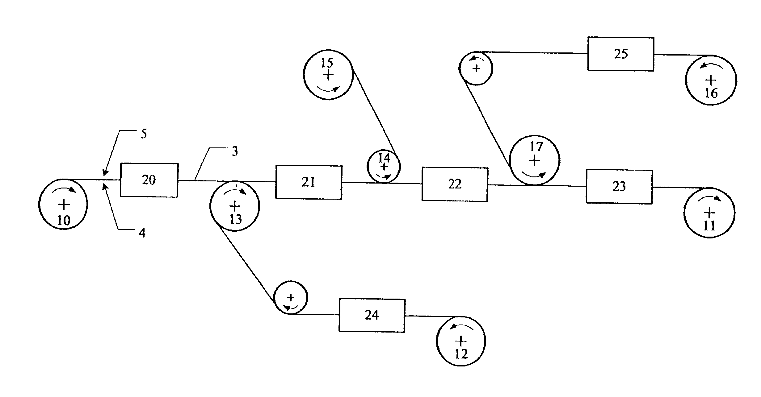
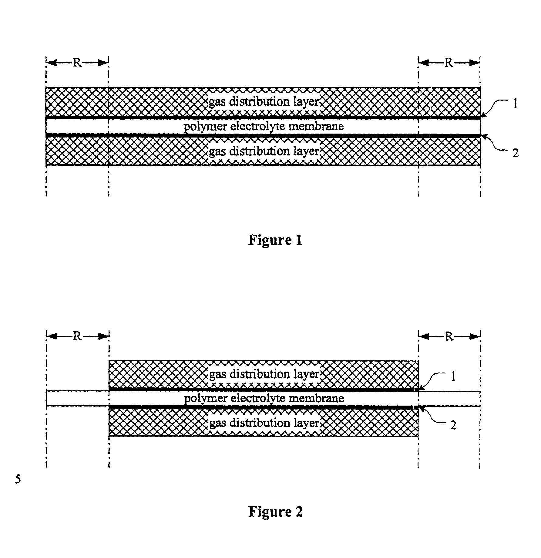
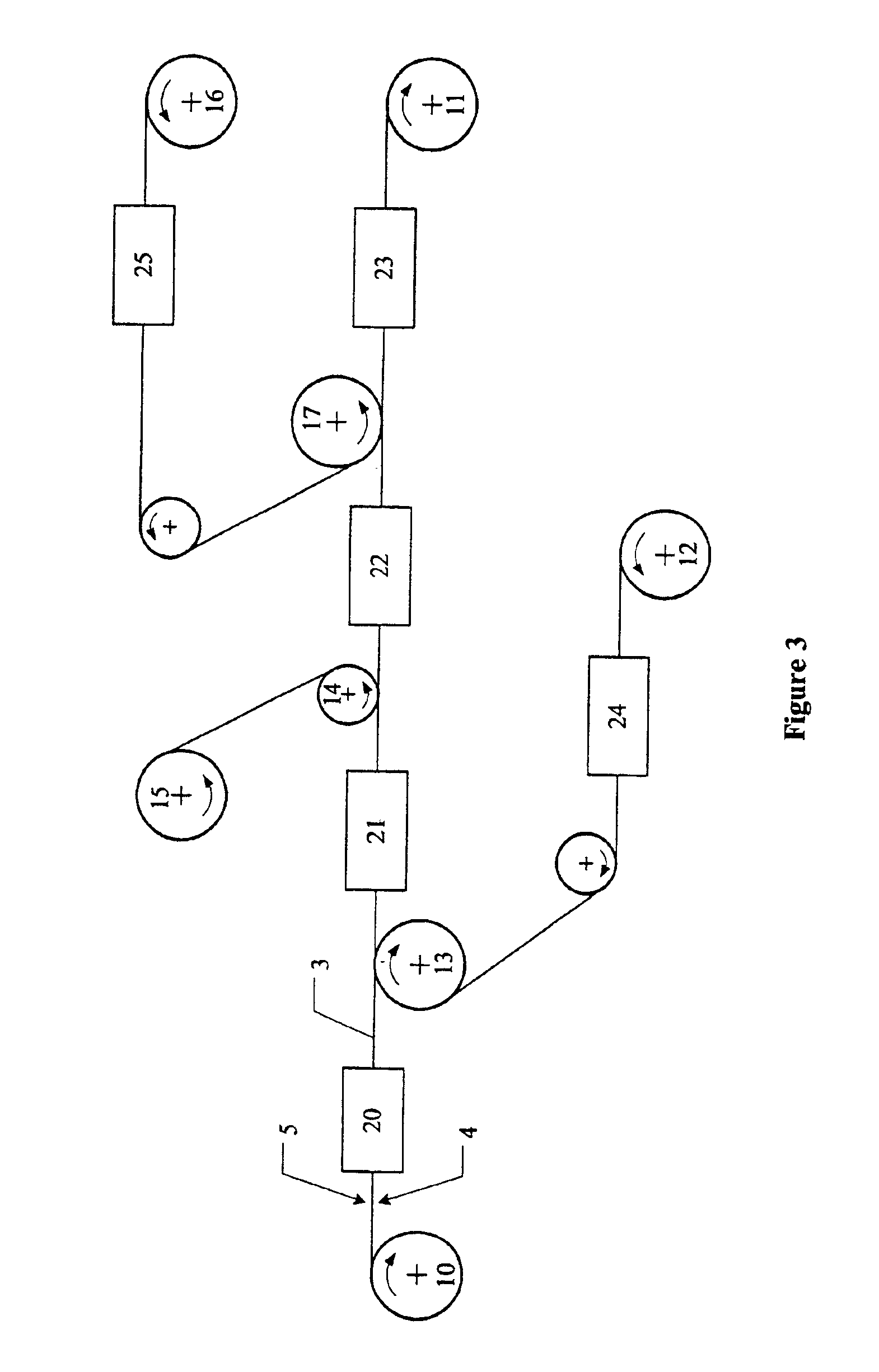
[0081]A 30 μm thick polymer electrolyte membrane, which was supported on one surface by a laminated film of polyester, was first coated on the readily accessible surface with the cathode ink. A water repellent carbon fiber paper (Toray TGPH-060) was laid on the still moist cathode layer. Then the composit...


PUM

PropertyMeasurementUnit
temperatureaaaaaaaaaa
thicknessaaaaaaaaaa
thicknessaaaaaaaaaa

Abstract

A process for producing a membrane electrode assembly for fuel cells containing a polymer electrolyte membrane having a first and a second surface parallel to each other. The first surface forms a firm composite with a first catalyst layer and a first water repellent gas distribution layer and said second surface form a firm composite with a second catalyst layer and a second water repellent gas distribution layer. The catalyst layers are prepared by using inks containing electrocatalysts, one or more solvents, proton-conducting ionomer and optionally water repelling agents and pore-forming agents. In the process the two catalyst layers are applied to or contacted with the respective surfaces of the polymer electrolyte membrane successively, wherein during the application or contacting process to one surface always the opposite surface of the membrane is supported.

Description

INTRODUCTION AND BACKGROUND[0001]The present invention provides a process for producing a membrane electrode assembly (MEA) for fuel cells, which is especially suitable for continuous manufacture of membrane electrode assemblies.[0002]A membrane electrode assembly consists of a polymer electrolyte membrane, both faces of which are each provided with a catalyst layer and a gas distribution layer arranged on top of the catalyst layer. One of the catalyst layers is designed as an anode for the oxidation of hydrogen and the second catalyst layer is designed as a cathode for the reduction of oxygen. The gas distribution layers normally consist of carbon fiber paper or carbon fiber fabric and enable good access by the reaction gases to the reaction layers and good conductance of the cell current. The catalyst layers for anode and cathode contain a proton-conducting polymer and so-called electrocatalysts which catalytically support the relevant reaction (oxidation of hydrogen and reduction...

Claims


Application Information

Patent Timeline
Patent Type & Authority Patents(United States)
IPC IPC(8): B05D5/12H01M4/88H01M8/1004
CPCH01M4/881H01M4/8828H01M8/1004Y02E60/521H01M2300/0082H01M2008/1095Y02E60/50Y02P70/50H01M4/86H01M8/02
Inventor KOHLER, JOACHIMSTARZ, KARL-ANTONWITTPAHL, SANDRADIEHL, MANFRED
Owner UMICORE AG & CO KG
Why Eureka
Try Eureka