Integrated RFID and video tracking system

a video tracking system and integrated technology, applied in the field of surveillance systems, can solve the problems of rfid camera location determination system limitations, etc., and achieve the effects of improving the accuracy of rfid tracking system, and improving the accuracy of video location determination system

Inactive Publication Date: 2006-02-14
ACTIVEYE
View PDF11 Cites 114 Cited by
  • Summary
  • Abstract
  • Description
  • Claims
  • Application Information

AI Technical Summary

Benefits of technology

[0009]It is an object of this invention to combine the advantages provided by a video tracking system and an RFID tracking system to overcome the limitations of either system, or both. It is a further object of this invention to improve the accuracy of an RFID location determination system based on information provided by a video location determination system. It is a further object of this invention to improve the accuracy of a video location determination system based on information provided by an RFID location determination system.
[0010]These objects and others are achieved by integrating a video surveillance system with an RFID tracking system. The calibration of the RFID tracking system is enhanced by using information provided b...

Problems solved by technology

Camera location determining systems have a number of limitations, particularly in a complex physical environment that limits the fields of view of the video cameras, or limits the...

Method used


Image

  • Integrated RFID and video tracking system
  • Integrated RFID and video tracking system

Examples


Embodiment Construction

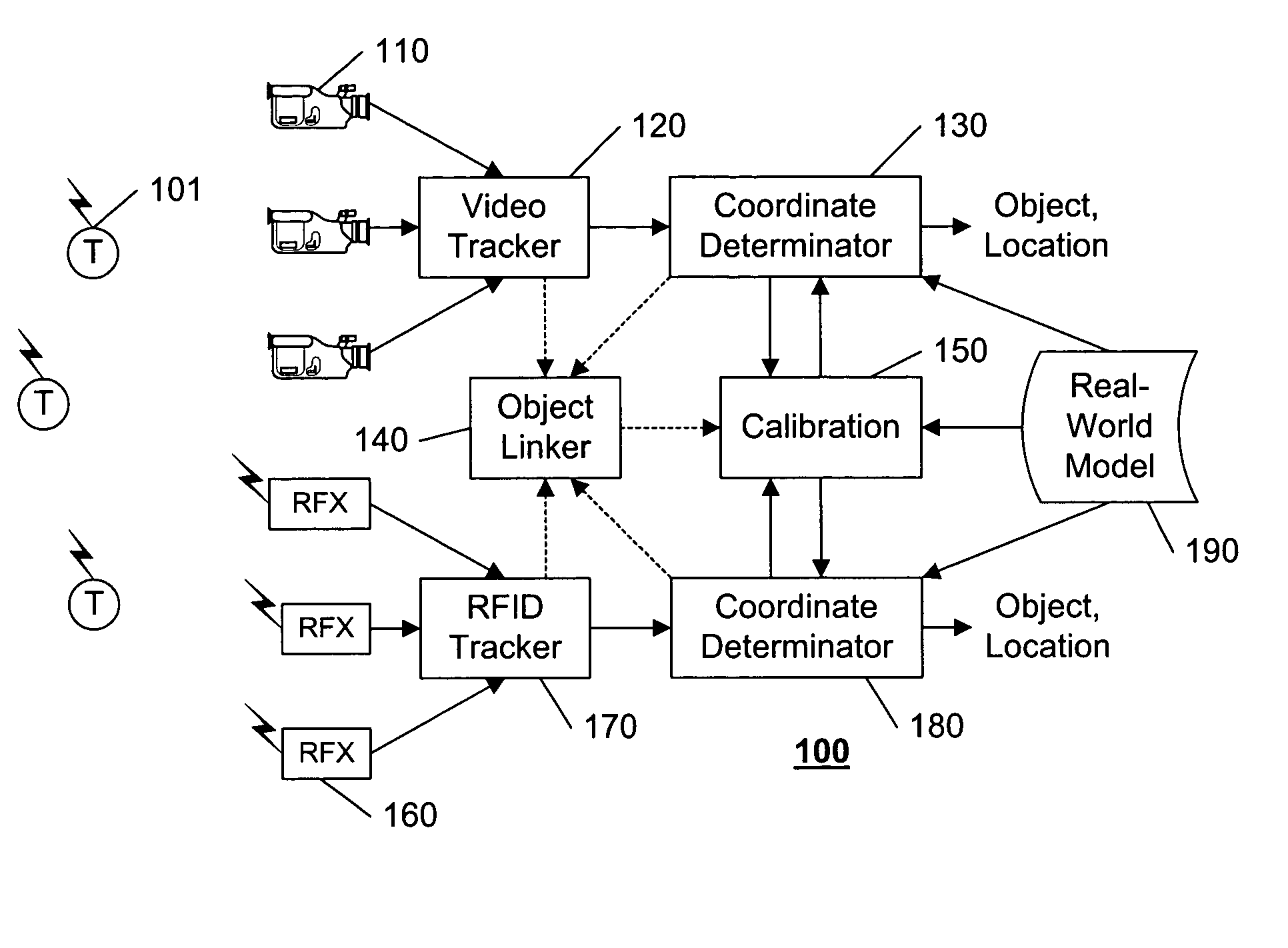
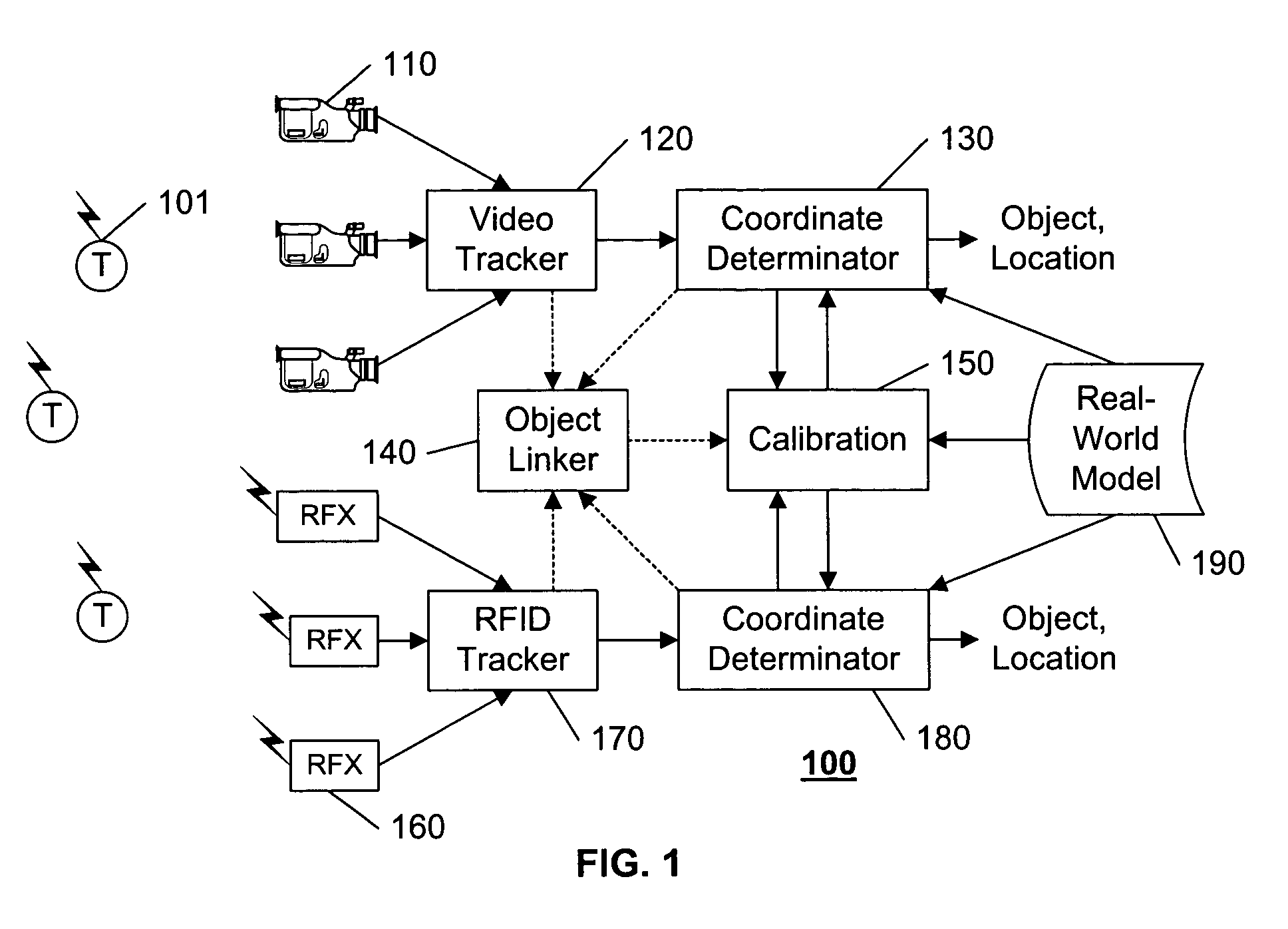
[0013]FIG. 1 illustrates an example integrated RFID and video surveillance system 100 in accordance with this invention.

[0014]The system 100 includes one or more cameras 110 that are coupled to a video tracking subsystem 120 for tracking objects that appear in the video scenes provided by the cameras 110. To facilitate reporting functions, the subsystem 120 is coupled to, or includes, a coordinate determinator 130 that maps the location of objects in the video scenes to “real-world” coordinates. These may be true real world coordinates, such as latitude, longitude, and altitude, or they may be coordinates relative to the particular surveillance area, or relative to an artificial field of reference, and so on; their main function being to convey information that can be used to identify where the object is actually located in the physical surveillance area. Typically, the coordinate determination is based on a real-world model 190, which may be explicit, such as a floor-plan of the su...


PUM


Abstract

A video surveillance system is integrated with an RFID tracking system. The calibration of the RFID tracking system is enhanced by using information provided by the video surveillance system. Optionally, the calibration of the video surveillance system may be enhanced by using information provided by the RFID tracking system. Calibration of the RFID tracking system is facilitated by placing RFID tags at visually apparent locations in a surveillance area and using the location information determined from the video surveillance system to determine appropriate correction factors for use in subsequent RFID location determinations. Dynamic performance is also calibrated by placing RFID tags on visually apparent moving targets and using the location information determined from the video surveillance system to determine the parameters used to qualify subsequent RFID location estimates of moving targets.

Description

[0001]This application claims the benefit of U.S. Provisional Patent Application 60 / 450,253, filed 26 Feb. 2003.BACKGROUND OF THE INVENTION[0002]1. Field of the Invention[0003]This invention relates to the field of surveillance systems, and in particular to a system that includes both RFID and Video tracking capabilities. Of particular note, this invention addresses the joint calibration of such systems and the subsequent application of this calibration in tracking objects in a surveillance area.[0004]2. Description of Related Art[0005]The use of video cameras for tracking objects in a surveillance area is common in the art. The “actual” location of an object (also commonly referred to as the “real-world” coordinates of the object, the “physical” location of the object, the “3-D” coordinates of the object, and so on) is determined from the appearance of the object in the field of view of one or more cameras based on a “calibration” of the one or more cameras with respect to the phys...

Claims


Application Information

Patent Timeline
IPC IPC(8): G08B23/00G08B13/196G01S19/35H04N7/18
CPCG08B13/19608H04N7/183G08B13/19697G08B13/19645G06V20/52G06F18/251
Inventor LIN, YUN-TING
Owner ACTIVEYE
Why Eureka
Try Eureka