Image-capturing element, image-capturing circuit for processing signal from image-capturing element, image-capturing device, driving method of image-capturing element

Inactive Publication Date: 2006-02-14
NIKON CORP
View PDF7 Cites 109 Cited by
  • Summary
  • Abstract
  • Description
  • Claims
  • Application Information

AI Technical Summary

Benefits of technology

[0031]The first object of the present invention is to provide an image-capturing element in which both color image and black and white image can be captured with the identical image-capturin

Problems solved by technology

However, when a signal processing circuit converts the color image described above to a black and white image, a problem arises in that black and white image output cannot be obtained promptly since the color image-capture signal must first undergo A/D conversion to become converted to a digital signal, which must then be temporarily stored in memory and a significant length of time is required for the arithmetic operation in signal processing performed by the signal processing circuit or in the signal processing software to convert the color image to a black and white image.
In particular, in the case of an electronic camera that performs such processing, due to the fact that the black and white images cannot be output at high speed, high speed continuous photographing (continuous shooting) cannot be achieved.
However, it is necessary to further increase the number of pixels to improve the sensitivity by adding the electrical charges at the pixels while maintaining the resolution at a specific level or higher using primary color filters i.e., red (R), green (G) and blue (B) filters and, at the same time, an increase in the number of pixels causes a problem in that the quantity of electrical charge that can be handled by each pixel is reduced due to restrictions related to the layout of the pixels and the electrical charge transfer path resulting in a reduced degree of sensitivity and a reduction in the dynamic range of the photoelectric conversion.
Howeve

Method used


Image

  • Image-capturing element, image-capturing circuit for processing signal from image-capturing element, image-capturing device, driving method of image-capturing element
  • Image-capturing element, image-capturing circuit for processing signal from image-capturing element, image-capturing device, driving method of image-capturing element
  • Image-capturing element, image-capturing circuit for processing signal from image-capturing element, image-capturing device, driving method of image-capturing element

Examples


first embodiment

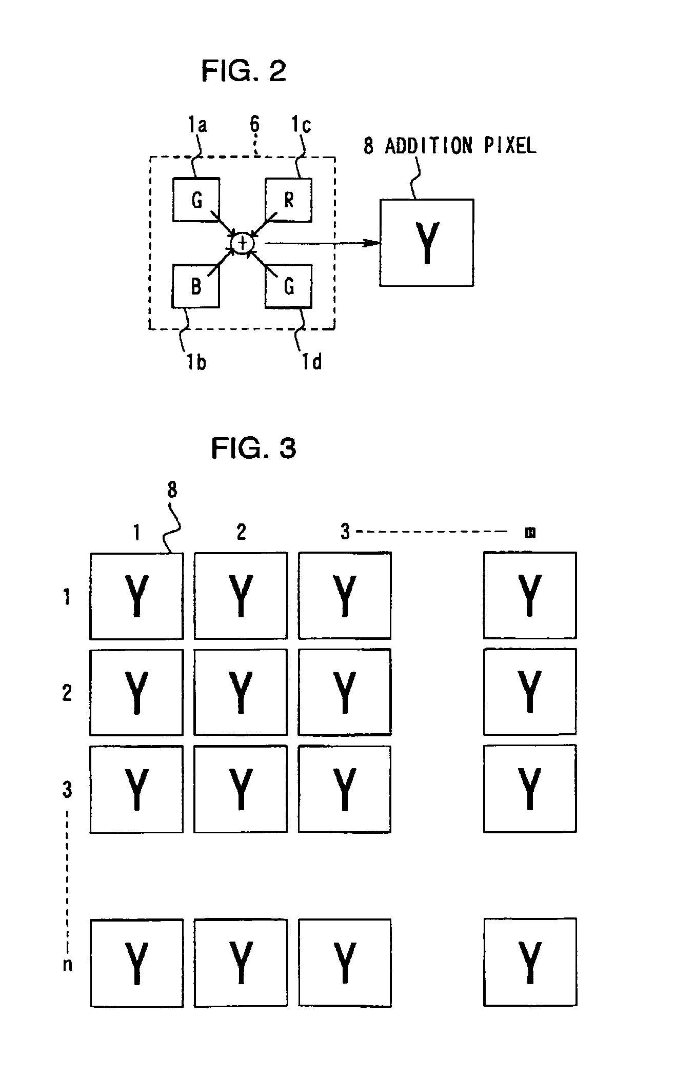
[0102]The following is an explanation of the first embodiment of the present invention given in reference to the drawings. The image-capturing element in the first embodiment makes it possible to capture both a color image and a black and white image with a single image-capturing element and also makes it possible to achieve high speed image-capturing for black and white images by performing appropriate addition of pixels.

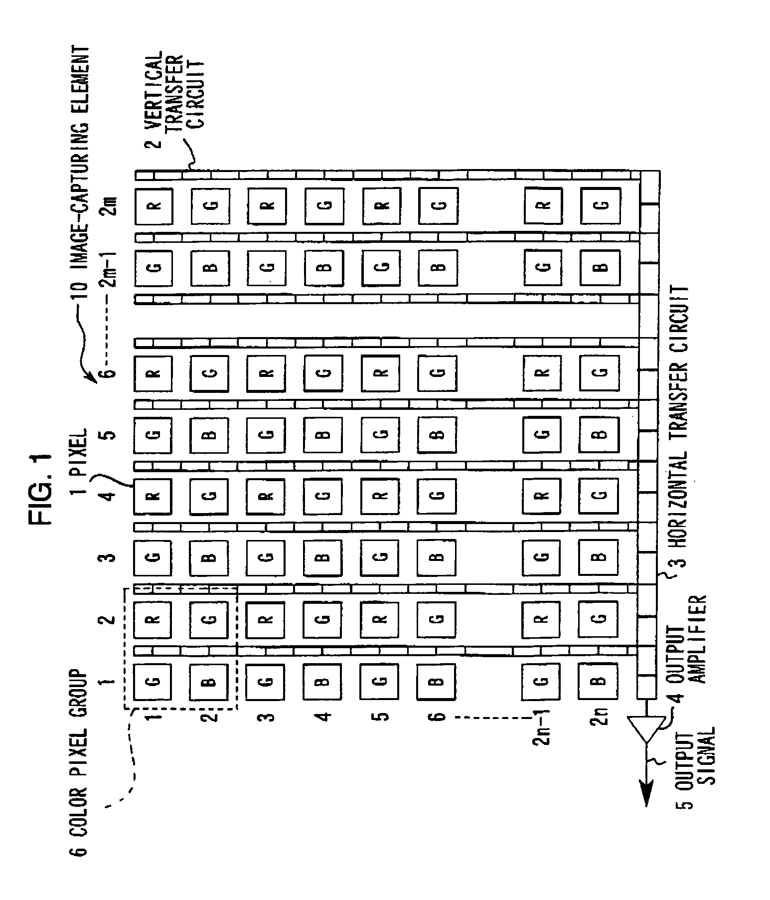
[0103]FIG. 1 illustrates the structure of the image-capturing element in the first embodiment. An image-capturing element 10 constitutes a color pixel matrix achieved by arraying a plurality of pixels 1, i.e., 2m pixels 1 in the horizontal direction (the direction of rows) and 2n pixels 1 in the vertical direction (the direction of columns). The color pixel matrix, which is achieved through an RGB Bayer array of R, C and B color pixels, is constituted of a plurality of color pixel groups 6, m of which are provided in the horizontal direction and n of which are prov...

second embodiment

[0153]The following is an explanation of the second embodiment of the present invention given in reference to the drawings. The image capturing element in the second embodiment achieves an improvement in the dynamic range while maintaining a high degree of sensitivity by appropriately adding pixels.

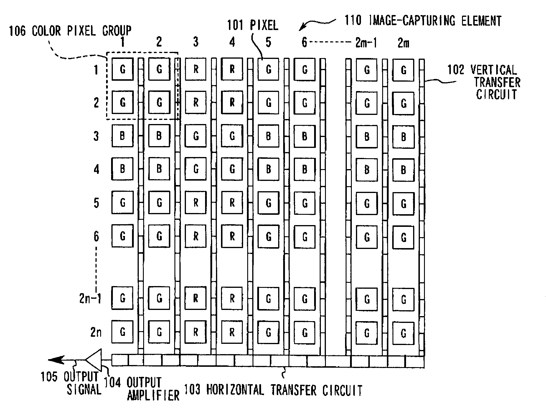
[0154]FIG. 6 illustrates the structure of the image-capturing element in the second embodiment. An image-capturing element 110 constitutes a color pixel matrix achieved by arraying a plurality of pixels 101, 2m of which are provided in the horizontal direction (the direction of rows) and 2n of which are provided in the vertical direction (the direction of columns). The color pixel matrix is constituted of m×n color pixel groups 106 in each of which all of the 2×2 pixels i.e., the four pixels adjacent to each other vertically and horizontally, are of a single color component.

[0155]When the color pixel matrix is regarded in units of the m×n individual color pixel groups 106, the color pixel...

third embodiment

[0180]The following is an explanation of the third embodiment given in reference to the drawings. In the image-capturing element in the third embodiment, an image-capture signal with a wide dynamic range is achieved through appropriate synthesis (or composition), addition and the like of pixels.

[0181]FIG. 9 illustrates the structure of the image-capturing element in the third embodiment. An image-capturing element 210 constitutes a color pixel matrix achieved by arraying a plurality of pixels 201, 2m of which are provided in the horizontal direction (the direction of rows) and 2n of which are provided in the vertical direction (the direction of columns). The color pixel matrix is constituted of m×n color pixel groups 206 in each of which all of the 2×2 pixels i.e., the four pixels adjacent to each other vertically and horizontally are of a single color component.

[0182]When the color pixel matrix is regarded in units of the m×n individual color pixel groups 206, the color pixel matri...


PUM


Abstract

An image-capturing element comprises: a plurality of pixels provided in a matrix each of which has a photoelectric conversion element; a plurality of color filters each of which is provided at one of the plurality of pixels; and a read out circuit that adds together electrical charges of pixels within every specific range among the plurality of pixels and enables a sequential read out of added electrical charges.

Description

[0001]This is a continuation-in-part of U.S. patent application Ser. No. 09 / 288,654 filed Apr. 9, 1999.INCORPORATION BY REFERENCE[0002]The disclosures of the following priority applications are herein incorporated by reference:[0003]Japanese Patent Application NO. 10-116266 filed Apr. 10, 1998[0004]Japanese Patent Application No. 10-116267 filed Apr. 10, 1998[0005]Japanese Patent Application No. 10-116268 filed Apr. 10, 1998[0006]Japanese Patent Application No. 10-249198 filed Aug. 19, 1998[0007]Japanese Patent Application No. 10-317896 filed November 9, 1998BACKGROUND OF THE INVENTION[0008]1. Field of the Invention[0009]The present invention relates to an image-capturing element, an image-capturing circuit for processing an image-capture signal provided by an image-capturing element, an image-capturing device employing the image-capturing element and / or the image-capturing circuit, and a driving method of the image-capturing element.[0010]2. Description of the Related Art[0011]When...

Claims


Application Information

Patent Timeline
IPC IPC(8): H04N3/14H04N5/235
CPCH04N9/045H04N25/585H04N25/77
Inventor SHIBAZAKI, KIYOSHIGESUZUKI, MASAHIRO
Owner NIKON CORP
Why Eureka
Try Eureka