Polarization rotator, parallax barrier, display and optical modulator

Active Publication Date: 2006-02-14
SHARP KK
View PDF7 Cites 17 Cited by
  • Summary
  • Abstract
  • Description
  • Claims
  • Application Information

AI Technical Summary

Benefits of technology

[0028]It has been found that a TN LCD with a 90° twist can be used to rotate the plane of polarization of linearly polarized light by any arbitrary angle. The effect may be modulated (between providing polarization rotation and providing no polarization rotation) by means of a relatively low finite voltage. Such a device has many applications, for example as part of a parallax barrier in a switchable 2D/autostereoscopic 3D display and as an optical modulator in an optical telecommunications system.
[0029]Through

Problems solved by technology

However, this self-compensation on

Method used


Image

  • Polarization rotator, parallax barrier, display and optical modulator
  • Polarization rotator, parallax barrier, display and optical modulator
  • Polarization rotator, parallax barrier, display and optical modulator

Examples


Example

[0041]Like reference numerals refer to like parts throughout the drawings.

DESCRIPTION OF THE PREFERRED EMBODIMENTS

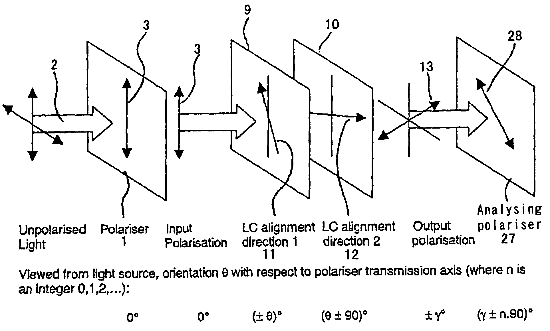
[0042]It is possible to derive conditions for which an LCD converts a first linear polarization to any arbitrary different linear polarization of light, such as visible light, based on the technique disclosed by Beynon et al, Journal of the SID 1999, 7, 71. By setting the twist angle φ to + or −90° (+ or −π / 2), the following condition relates the angle γ of rotation of the linear polarization azimuth (with respect to the incident polarization azimuth) to the retardation of a nematic liquid crystal layer: tan⁡[±π2-γ]=tan⁡[±π2·1+α2]1+α2α=±2·Δ⁢⁢n·dλ2⁢⁢θ=γ∓π2

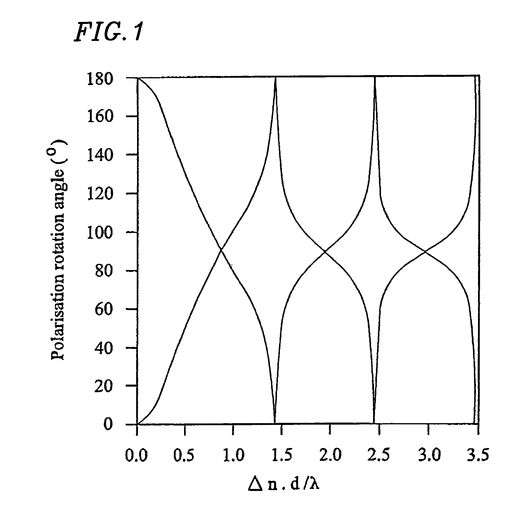
where d is the thickness of the layer, λ is the wavelength of light, Δn is the birefringence of the liquid crystal material, and θ is the angle between the azimuth of the incident linear polarization and the input director of the liquid crystal. This is represented graphically in FIG. 1, which plots the rotation angle γ ...


PUM


Abstract

A polarization rotator is provided for rotating the polarization direction of linearly polarized light by any arbitrary angle other than 90°. The device comprises a layer of liquid crystal material disposed between alignment surfaces. In one mode, a 90° twist is induced in the liquid crystal director. An expression is provided for relating the retardation of the layer to the amount of polarization rotation and the angle between the polarization direction of incident light and the alignment direction at the input side of the liquid crystal layer.

Description

BACKGROUND OF THE INVENTION[0001]1. Field of the Invention[0002]The present invention relates to a polarization rotator for rotating the plane of polarization of linearly polarized light by an arbitrary angle. Such a rotator may be used, for example, as part of a parallax barrier in a display or as an optical modulator in telecommunications. The present invention also relates to parallax barriers, displays and optical modulators including such polarization rotators.[0003]2. Description of the Related Art[0004]A known type of liquid crystal device (LCD) is the twisted nematic (TN) type. In such a device, a layer of nematic liquid crystal material is disposed between opposing alignment surfaces, such as rubbed polyimide, which cause the liquid crystal director to twist through 90° from one alignment surface to the other in the absence of an applied field. In the absence of an applied field, the plane of linearly polarized light passing through the device is rotated by 90°.[0005]A rela...

Claims


Application Information

Patent Timeline
IPC IPC(8): G02F1/139G02B27/28G02F1/13G02F1/01G02F1/1335G02F1/13363H04N13/00
CPCG02B27/286G02F1/0136H04N13/0454H04N13/0409G02F1/1396G02F2001/133531H04N13/31H04N13/359G02F1/133531G02F1/13363
Inventor TILLIN, MARTIN DAVIDJACOBS, ADRIAN MARC SIMON
Owner SHARP KK
Why Eureka
Try Eureka