Temperature sensing circuit

a temperature sensing circuit and circuit technology, applied in the field of temperature sensing technology, can solve problems such as inaccuracy in temperature sensing, and achieve the effect of improving the accuracy of temperature sensing and reducing the channel length modulation

Pending Publication Date: 2021-07-22
REALTEK SEMICON CORP
View PDF17 Cites 2 Cited by
  • Summary
  • Abstract
  • Description
  • Claims
  • Application Information

AI Technical Summary

Benefits of technology

[0008]When the temperature sensing circuit of the present disclosure completes the sensing, the voltages used for comparison to sense the temperature are equal to each other, thereby eliminating the channel length modulation effect between the transistors used to generate the two voltages and greatly improving the accuracy of temperature sensing.

Problems solved by technology

However, common temperature sensing circuits, whether they use a delay line to generate a signal with a time difference for temperature sensing, or use a current difference between current mirror branches for temperature sensing, are susceptible to the process deviation of the metal-oxide-semiconductor transistor in the circuit or the effect of channel length modulation, which lead to inaccurate temperature sensing.
Therefore, how to design a new temperature sensing circuit to solve the above-mentioned shortcomings is an urgent issue for the industry.

Method used


Image

  • Temperature sensing circuit
  • Temperature sensing circuit
  • Temperature sensing circuit

Examples


Embodiment Construction

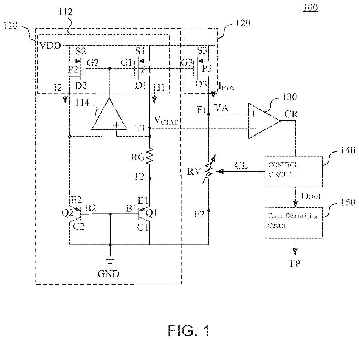
[0014]Reference is made to FIG. 1. FIG. 1 is a circuit diagram of a temperature sensing circuit 100 according to an embodiment of the present disclosure. The temperature sensing circuit 100 includes a band gap voltage generating circuit 110, a current mirror branch 120, a variable resistor RV, a comparison circuit 130, a control circuit 140, and a temperature determining circuit 150.

[0015]The band gap voltage generating circuit 110 is configured to generate a band gap voltage VCTAT having a first temperature coefficient. In one embodiment, the band gap voltage generating circuit 110 includes a current source circuit 112, a resistor RG, a pair of bipolar junction transistors Q1, Q2, and a voltage equalization circuit 114.

[0016]In one embodiment, the current source circuit 112 includes a first current source branch corresponding to the first current output terminal and a second current source branch corresponding to the second current output terminal. The first current source branch i...


PUM

PropertyMeasurementUnit
band gap voltageaaaaaaaaaa
temperature coefficientaaaaaaaaaa
band gapaaaaaaaaaa

Abstract

A temperature sensing circuit that includes a bandgap voltage generation circuit, a current mirror branch, a variable resistor, a comparator circuit, a control circuit and a temperature determining circuit. The bandgap voltage generation circuit generates a bandgap voltage. The current mirror branch generates a mirrored current mirrored from the bandgap voltage generation circuit. The variable resistor is electrically coupled to the current mirror branch to receive the mirrored current to generate a variable voltage. The comparator circuit compares the bandgap voltage and the variable voltage to generate a comparison result. The control circuit generates a control signal according to the comparison result to adjust the resistance of the variable resistor and outputs a signal value when the signal value forces the variable voltage to be equal to the bandgap voltage. The temperature determining circuit generates a temperature value according to the signal value.

Description

CROSS-REFERENCE TO RELATED APPLICATION[0001]This application claims priority to Taiwan Application Serial Number 109102017, filed Jan. 20, 2020, which is herein incorporated by reference in its entirety.BACKGROUNDField of Invention[0002]The present disclosure relates to a temperature sensing technology, and in particular, to a temperature sensing circuit.Description of Related Art[0003]In low-voltage system-on-a-chip circuits, the temperature inside the chip can be sensed using characteristics that vary with time or that the signal delay varies with temperature. However, common temperature sensing circuits, whether they use a delay line to generate a signal with a time difference for temperature sensing, or use a current difference between current mirror branches for temperature sensing, are susceptible to the process deviation of the metal-oxide-semiconductor transistor in the circuit or the effect of channel length modulation, which lead to inaccurate temperature sensing.[0004]The...

Claims


Application Information

Patent Timeline
Patent Type & Authority Applications(United States)
IPC IPC(8): G01K7/00
CPCG01K7/00G01K7/01
Inventor TU, CHIH-CHANCHEN, CHIH-LUNG
Owner REALTEK SEMICON CORP
Why Eureka
Try Eureka