
Device for Encapsulating Fiber Bragg Grating Temperature Sensing Probe on Electric Energy Meter Terminal and Integrated Temperature Calibration Method

A terminal block and optical fiber grating technology, which is applied in the field of temperature monitoring of electric energy meters, can solve the problems of inaccurate temperature measurement, unstable working status, and difficulty in observing the working conditions of electric energy meter contacts, so as to improve the temperature sensing accuracy and avoid overheating Effects of calibration error, improvement of response speed and measurement accuracy

Active Publication Date: 2017-01-18
NANJING UNIV OF AERONAUTICS & ASTRONAUTICS
View PDF5 Cites 0 Cited by
  • Summary
  • Abstract
  • Description
  • Claims
  • Application Information

AI Technical Summary

Problems solved by technology

It is difficult for inspectors to observe the working conditions of the contacts of the electric energy meter by conventional inspection methods
[0003] Conventional electric energy meter temperature measurement equipment is a non-contact temperature measurement instrument, which is easily affected by electromagnetic fields and external environmental temperature factors, resulting in inaccurate temperature measurement and unstable working conditions.

Method used


Image

  • Device for Encapsulating Fiber Bragg Grating Temperature Sensing Probe on Electric Energy Meter Terminal and Integrated Temperature Calibration Method
  • Device for Encapsulating Fiber Bragg Grating Temperature Sensing Probe on Electric Energy Meter Terminal and Integrated Temperature Calibration Method
  • Device for Encapsulating Fiber Bragg Grating Temperature Sensing Probe on Electric Energy Meter Terminal and Integrated Temperature Calibration Method

Examples


Embodiment Construction

[0019] Below in conjunction with accompanying drawing, the technical scheme of invention is described in detail:

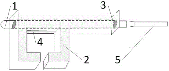
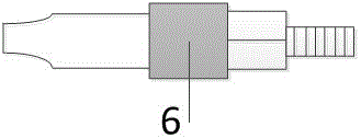
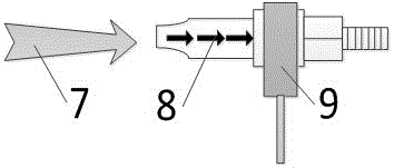
[0020] see figure 1 , a device for encapsulating a fiber grating temperature-sensing probe on an electric energy meter terminal based on a back-shaped card slot structure. The main body of the device is a back-shaped card slot 2 made of a heat-conducting material, and one side of the card slot 2 runs through There is a built-in cylindrical hole for inserting the fiber grating temperature probe, which is used to fix the entire fiber grating temperature probe 1 to the contact of the electric energy meter and can effectively and quickly conduct the heat of the contact. The return type card slot 2 The shape and size of the inner hole correspond to the connection terminals of the electric energy meter. There is a bar-shaped opening area on the inner side of the card slot side that runs through the embedded cylindrical hole 3, and the opening area communicates with th...


PUM


Abstract

The invention provides a device for packaging a fiber grating temperature-sensing probe on a connection terminal of an electric energy meter and an integrated temperature calibration method thereof. The main body of the device is a back-shaped card slot made of heat-conducting material, and one side of the card slot is penetrated with an embedded cylindrical hole suitable for inserting a fiber grating temperature-sensing probe. The shape and size of the inner hole of the return-type card slot match the connection terminal of the electric energy meter. A bar-shaped opening area is designed on the inside of the back-type card slot to ensure that the fiber grating temperature-sensing probe and the electric energy meter terminal can maintain maximum direct contact. The whole device has a simple structure, can accurately sense the actual temperature information of the contacts in real time, and is easy to install. In addition, the overall temperature calibration method corresponding to this package is to use a constant temperature water bath device to perform point-by-point temperature calibration on the whole, so as to obtain the fiber grating temperature probe based on the back-shaped card slot structure and package the fiber grating at different temperatures Corresponding relationship between center wavelength offset and temperature change of the terminal under test.

Description

technical field [0001] The invention belongs to the field of temperature monitoring of electric energy meters, and in particular relates to a structure for packaging an optical fiber grating temperature-sensing probe on an electric energy meter terminal and a supporting integrated temperature calibration method. Background technique [0002] In the field of electric energy meter equipment, the terminal block of electric energy meter is the weak link that is prone to failure. After long-term use, due to poor contact at these parts, improper insertion eccentricity and other reasons, the contact resistance is relatively large. In the case of high current, the heating here is serious, and the result is that the temperature of the joint is abnormal. As a result, the oxidation of the contact surface is aggravated, and the contact resistance is further increased, forming a vicious circle, thereby damaging the terminals of the electric energy meter. It is difficult for inspectors ...

Claims


Application Information

Patent Timeline
Patent Type & Authority Patents(China)
IPC IPC(8): G01K11/32G01K1/14G01K15/00G01K11/3206
Inventor 曾捷曹海东王馨毛超群刘苏州张先辉
Owner NANJING UNIV OF AERONAUTICS & ASTRONAUTICS
Learn More