Temperature sensing circuit

a temperature sensing circuit and temperature technology, applied in the field of temperature sensing technology, can solve problems such as inaccurate temperature sensing, and achieve the effect of vastly improving the accuracy of temperature sensing

Active Publication Date: 2021-07-22
REALTEK SEMICON CORP
View PDF2 Cites 0 Cited by
  • Summary
  • Abstract
  • Description
  • Claims
  • Application Information

AI Technical Summary

Benefits of technology

[0006]The temperature sensing circuit in the present disclosure avoids being affected by the manufacturing process of the metal oxide field effect transistors or the channel length modulation, and calculates time span by high accuracy clock signal to acquire the temperature value, such that the accuracy of the temperature sensing is vastly improved.

Problems solved by technology

However, common temperature sensing circuits either utilizing a delay line to generate signal with time difference for temperature sensing, or utilizing current difference between current mirrors for temperature sensing, are easily affected by the manufacturing process of the metal oxide field effect transistors in circuits, or by the channel length modulation, resulting in that the temperature sensing may be inaccurate.
Therefore, how to design a new temperature sensing circuit to overcome the disadvantages mentioned above is a problem waiting to be solved for the industries.

Method used


Image

  • Temperature sensing circuit
  • Temperature sensing circuit

Examples


Embodiment Construction

[0011]All the terms used in this document generally have their ordinary meanings. The examples of using any terms discussed herein such as those defined in commonly used dictionaries are illustrative only, and should not limit the scope and meaning of the disclosure. Likewise, the present disclosure is not limited to some embodiments given in this document.

[0012]In this document, it may be understood that the terms “first,”“second,” and “third” are to describe the various elements, components, zones, levels and / or blocks. However, these elements, components, zones, levels and / or blocks should not be limited by these terms. These terms are used to distinguish one element, component, zone, level and / or block from another. For example, a first element, component, zone, level and / or block may be termed a second element, component, zone, level and / or block without departing from the scope of the present disclosure. As used herein, the term “and / or” includes any and all combinations of on...


PUM

PropertyMeasurementUnit
currentaaaaaaaaaa
voltagesaaaaaaaaaa
temperature coefficientaaaaaaaaaa

Abstract

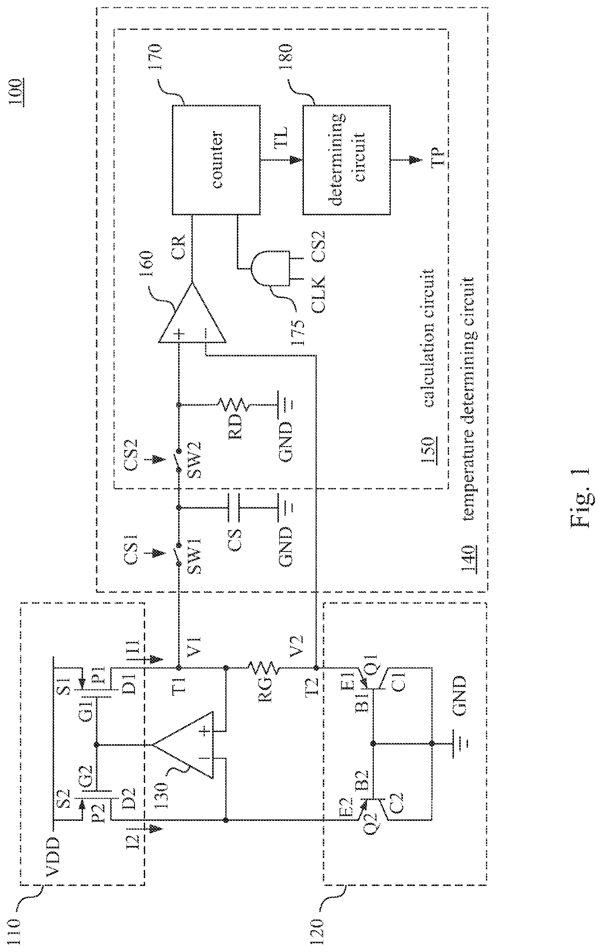
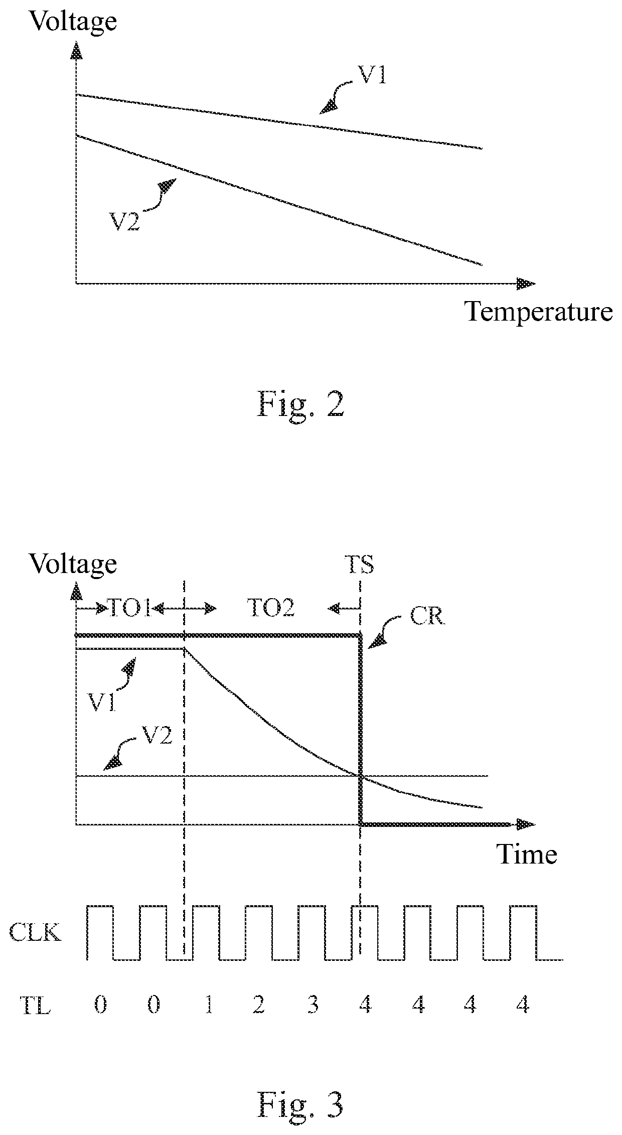
A temperature sensing circuit includes a current source circuit, a resistor, a bandgap voltage generation circuit, a voltage-equalizing circuit and a temperature determining circuit. The current source circuit has a first current output terminal and a second current output terminal. The bandgap voltage generation circuit includes a pair of bipolar junction transistors. The voltage-equalizing circuit equalizes voltages of a first current output terminal and the second current output terminal. The temperature determining circuit includes a sampling capacitor and a calculation circuit. The sampling capacitor samples a first voltage of a first terminal of the resistor and a second voltage of a second terminal of the resistor. The calculation circuit generates a temperature value by calculating a voltage difference between the first voltage and the second voltage.

Description

RELATED APPLICATION[0001]The present application claims priority to Taiwan Application Serial Number 109102016, filed Jan. 20, 2020, which is incorporated herein by reference in its entirety.BACKGROUNDTechnical Field[0002]The present disclosure relates to a temperature sensing technology. More particularly, the present disclosure relates to a temperature sensing circuit.Description of Related Art[0003]In a low voltage single chip circuit system, characteristics of time variations or signal delays that are different along with temperatures are applied to sense temperature inside the chip. However, common temperature sensing circuits either utilizing a delay line to generate signal with time difference for temperature sensing, or utilizing current difference between current mirrors for temperature sensing, are easily affected by the manufacturing process of the metal oxide field effect transistors in circuits, or by the channel length modulation, resulting in that the temperature sens...

Claims


Application Information

Patent Timeline
Patent Type & Authority Applications(United States)
IPC IPC(8): G01K7/24G05F3/26
CPCG01K7/24G05F3/267G01K7/01
Inventor TU, CHIH-CHAN
Owner REALTEK SEMICON CORP
Why Eureka
Try Eureka