Identical object determination method and apparatus and displacement correction method and apparatus

a technology of displacement correction and object determination, applied in the direction of distance measurement, navigation instruments, instruments, etc., can solve problems such as the inability to correct errors

Inactive Publication Date: 2006-02-14
FUJI JUKOGYO KK
View PDF24 Cites 28 Cited by
  • Summary
  • Abstract
  • Description
  • Claims
  • Application Information

AI Technical Summary

Benefits of technology

[0009]It is therefore an object of the present invention to effectively deter

Problems solved by technology

However, in the related arts, if an error occurs to such an extent to which the objects

Method used


Image

  • Identical object determination method and apparatus and displacement correction method and apparatus
  • Identical object determination method and apparatus and displacement correction method and apparatus
  • Identical object determination method and apparatus and displacement correction method and apparatus

Examples


first embodiment

(First Embodiment)

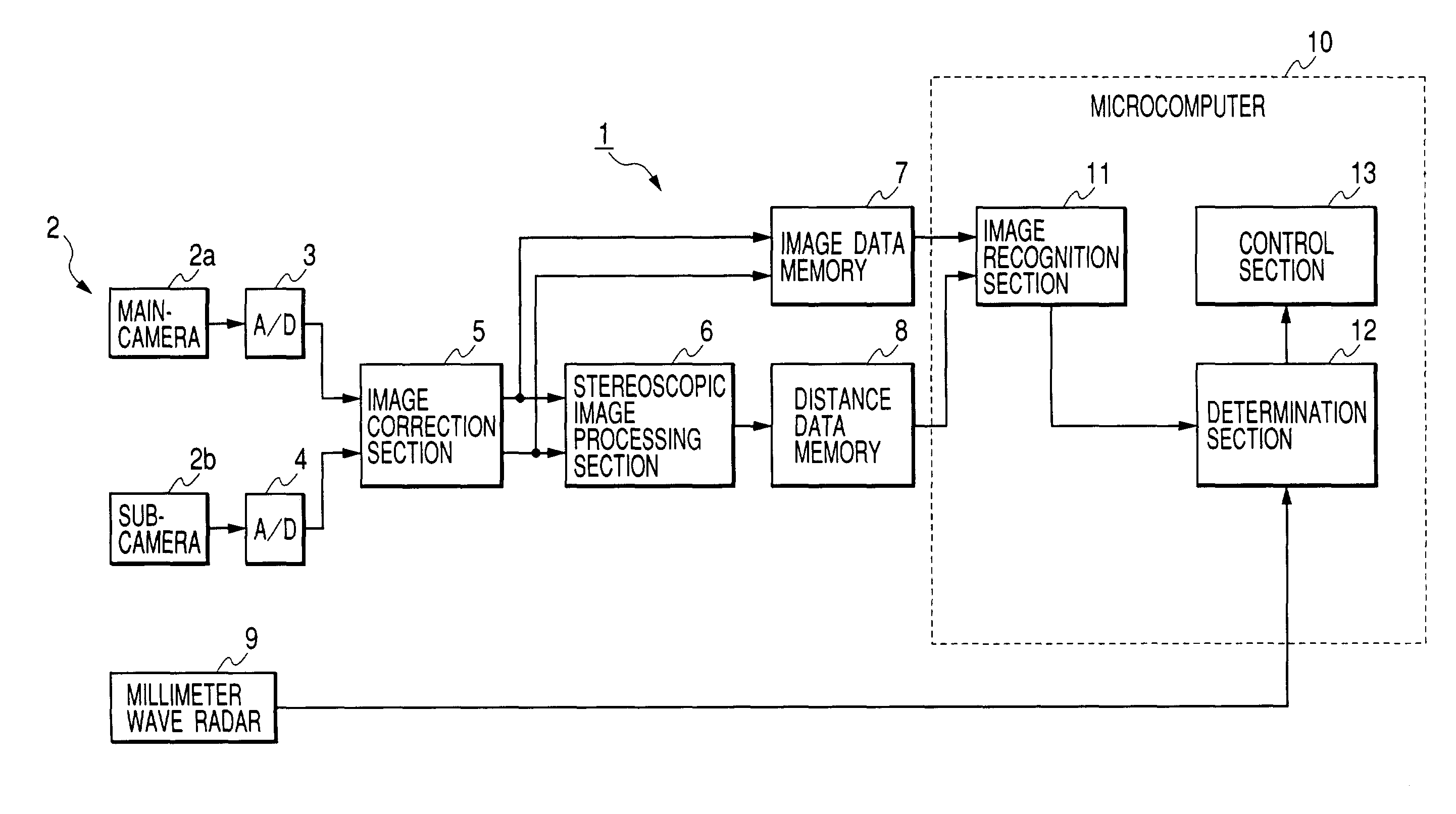
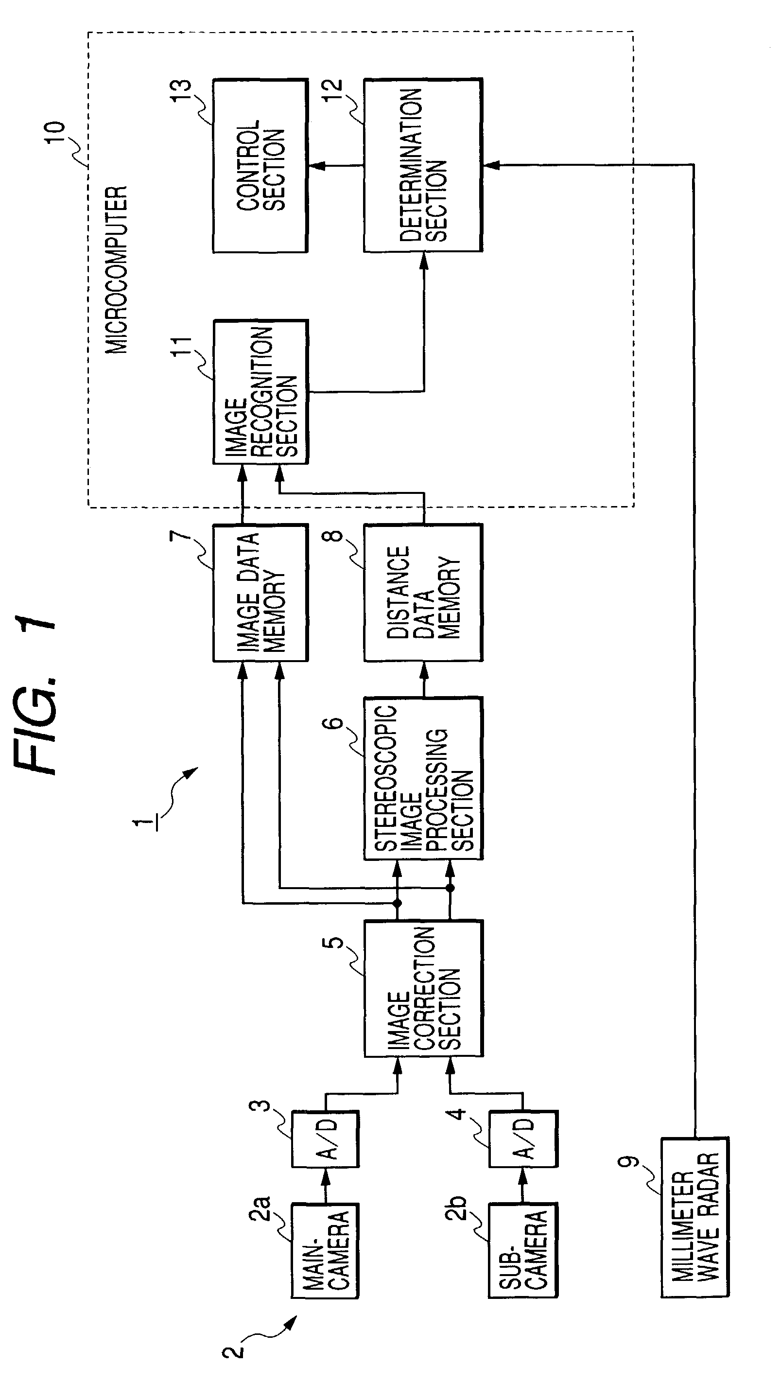
[0040]FIG. 1 is a block diagram of an identical object determination apparatus according to a first embodiment of the present invention. An identical object determination apparatus 1 according to the embodiment functions as a part of a monitoring system for monitoring the running circumstances ahead of a vehicle by way of example. The monitoring system uses a plurality of sensors in combination, determines whether or not the objects detected by the sensors are identical, and recognizes the running circumstances based on the determination result and detection information provided by the sensors.

[0041]The monitor system has a sensor for detecting an object based on a pair of picked-up images using stereoscopic image processing as one of the sensors (in the embodiment, two sensors), which will be hereinafter referred to as first sensor S1. A stereoscopic camera 2 functioning as a part of the first sensor S1 is installed at a reference position, for example, in the pro...

second embodiment

(Second Embodiment)

[0090]FIG. 8 is a block diagram of a displacement correction apparatus according to a second embodiment of the present invention. A displacement correction apparatus 1a according to the embodiment functions as a part of a monitoring system for monitoring the running circumstances ahead of a vehicle by way of example. The monitoring system uses a plurality of sensors, detects objects as the sensors collaborate, and recognizes the running circumstances based on the detection information. Further, the monitoring system corrects displacement of the identical objects detected by one sensor and any other sensor as the function of the displacement correction apparatus 1a. Components identical with those previously described with reference to FIG. 1 in the first embodiment are denoted by the same reference numerals in FIG. 8 and will not be discussed again in detail.

[0091]The second embodiment differs from the first embodiment in that displacement of the identical objects...

third embodiment

(Third Embodiment)

[0110]A third embodiment of the present invention differs from the second embodiment in that displacement of objects caused by the measurement time difference between the sensors is corrected. For example, to use a plurality of sensors, basically the detection timings of the sensors match. However, if the detection timings differ, particularly in a state in which the own vehicle turns, the relative positions of the objects detected by the sensors differ as the detection timings differ. If the sensors detect the identical object in such a state, there is a possibility that the objects detected by the sensors may be determined different because of the displacement.

[0111]Then, in the third embodiment, to correct an error caused by the measurement time difference, a yaw rate sensor is further included in addition to the components in the second embodiment. For example, in stereoscopic image processing, data is always delayed as long as the time required for image read ...


PUM


Abstract

An identical object determination method of determining whether or not objects are detected by a plurality of sensors identical has a determining a relative position and speed thereof, a determining a position error thereof based on the determined positions and calculating a first probability that the detected objects are identical with respect to the position from the determined position error based on a normal distribution concerning the position error, a determining a speed error thereof based on the determined speed and calculating a second probability that the detected objects are identical with respect to the speed from the determined speed error based on a normal distribution concerning the speed error, a calculating a third probability that the detected objects are identical based on the calculated first probability and the calculated second probability, and a determining that the detected objects are identical if the third probability exceeds a first determination value.

Description

BACKGROUND OF THE INVENTION[0001]1. Field of the Invention[0002]The present invention relates to an identical object determination method and apparatus for determining whether or not objects detected by a plurality of sensors are identical and a displacement correction method and apparatus for correcting relative displacement of identical objects.[0003]2. Description of the Related Art[0004]In recent years, a monitoring system for recognizing a situation in one area or monitoring the situation in the area based on the recognition result has received attention and has become commercially practical in various applications of vehicle outside monitoring, railroad crossing monitoring, topographic recognition, an altimeter, etc. In this kind of monitoring system, to detect an object existing in an area, various sensors of a sensor using stereoscopic image processing for calculating the parallax of the object based on a pair of picked-up images, a laser radar, a millimeter wave radar, etc....

Claims


Application Information

Patent Timeline
IPC IPC(8): G01S13/60G01C3/06B60R21/00G01S7/40G01S7/497G01S11/12G01S13/86G01S13/931G01S17/08G01S17/86G01S17/931
CPCG01S7/4026G01S7/497G01S13/931G01S13/865G01S13/867G01S17/936G01S11/12G01S2013/9375G01S17/023G01S2007/403G01S2013/93271G01S17/931G01S17/86G01S7/403
Inventor TAKAHASHI, YASUSHI
Owner FUJI JUKOGYO KK
Why Eureka
Try Eureka