Manifold for pack and a half condensing cycle pack with combined heat exchangers

a technology of condensing cycle pack and combined heat exchanger, which is applied in the direction of lighting and heating apparatus, domestic cooling apparatus, energy-efficient board measures, etc., can solve the problems of large operating inefficiencies, large weight, and large packaging requirements of aircraft, and achieve the effect of increasing reliability

Active Publication Date: 2006-02-21
HAMILTON SUNDSTRAND CORP
View PDF13 Cites 18 Cited by
  • Summary
  • Abstract
  • Description
  • Claims
  • Application Information

AI Technical Summary

Benefits of technology

[0010]The present invention provides an air generation unit including first and second air cycle machines (ACMs), each having first and second turbines. A manifold is arranged between the first and second ACMs and is in fluid communication with each of the first and second turbines of the first and second ACMs. A condenser is arranged between the ACMs and is in fluid communication with the manifold. First and second valves are disposed within the manifold and control flow of air between the turbines and the condenser. An actuator assembly is connected to the valves for moving the valves between a plurality of positions. The valves selectively close off or prevent the flow of air from the turbines of one of the ACMs in the event that the ACM is not needed or malfunctions.
[0011]Accordingly, the above invention provides an improved AGU having a small package, increased reliability, and sufficiently cooled air for the needs of a large aircraft.

Problems solved by technology

However, the design constraints for the aircraft require very small packaging with very high reliability.
The second prior art system AGU configuration provides sufficiently cold air, however, up to four or more AGUs would be required for such a large aircraft, which would necessitate removing significant aircraft structure and would significantly increase weight.
A dedicated solenoid valve is closed to prevent leakage from the turbine of the unwanted ACM, which would result in large operating inefficiencies.
As a result, with prior art AGUs, the number of components greatly increases as the number of turbines in an AGU increases resulting in higher costs and reduced reliability.

Method used


Image

  • Manifold for pack and a half condensing cycle pack with combined heat exchangers
  • Manifold for pack and a half condensing cycle pack with combined heat exchangers
  • Manifold for pack and a half condensing cycle pack with combined heat exchangers

Examples


Embodiment Construction

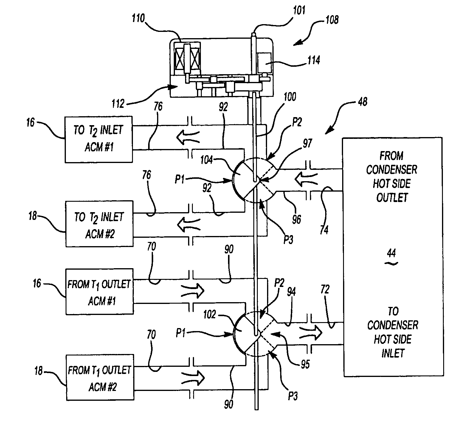
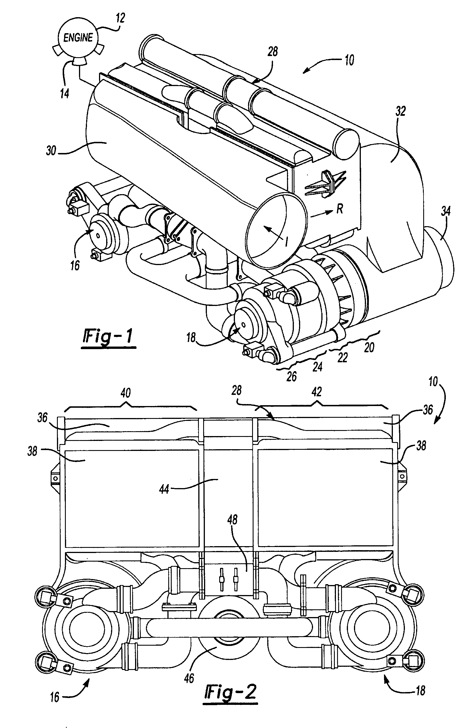
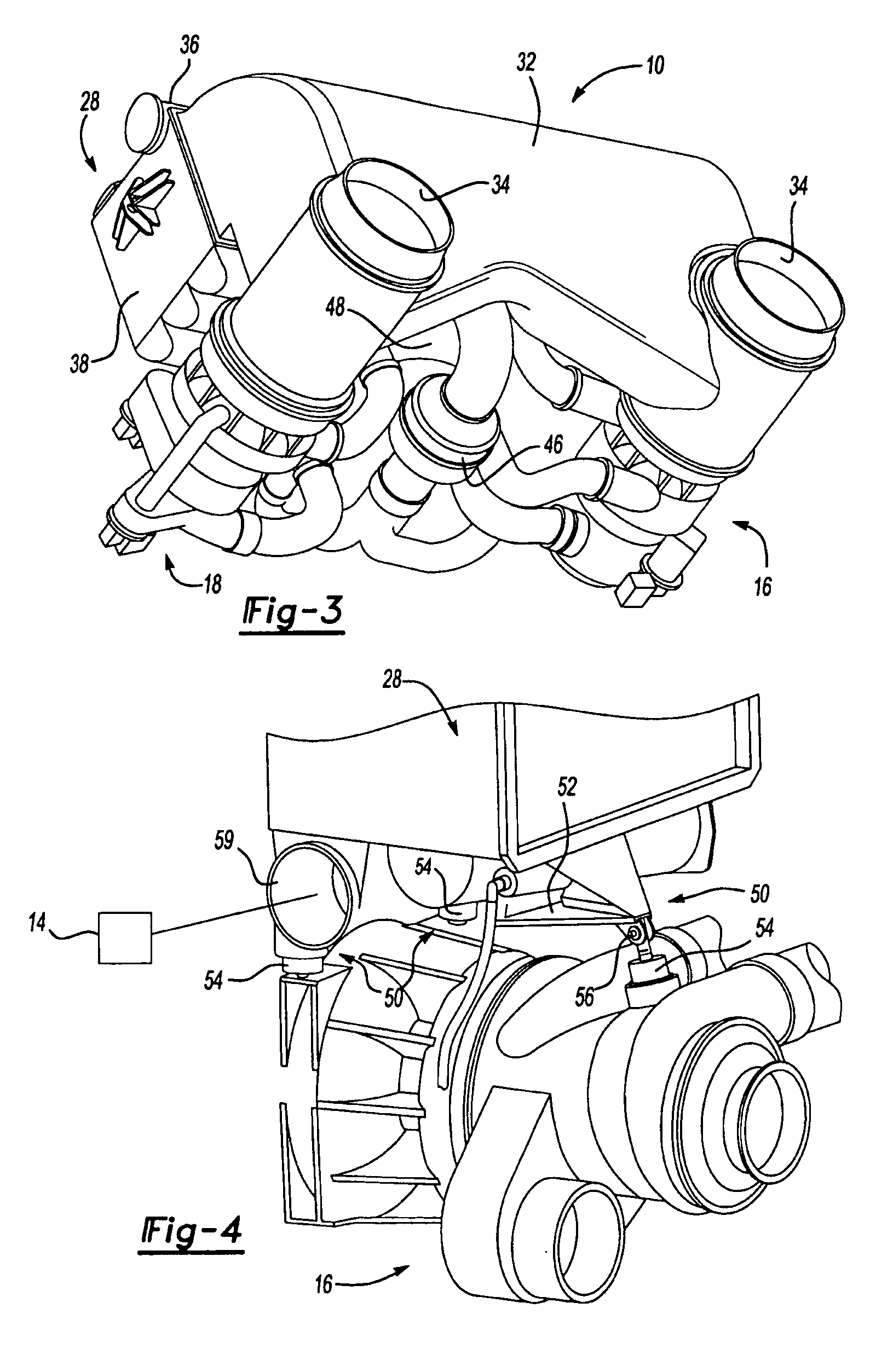
[0023]An air generation unit (AGU) 10 is shown in FIGS. 1-3. The AGU 10 receives pressurized air from an intermediate or high pressure stage of an engine 12 through a bleed valve 14. The pressurized air is conditioned by the AGU 10 to provide conditioned air to the aircraft.

[0024]The present invention AGU 10 includes first 16 and second 18 air cycle machines (ACM). The present invention ACMs 16 and 18 are a four wheel configuration including a fan 20, a compressor 22, and first 24 and second 26 turbines. The ACMs 16 and 18 are mechanically mounted to a shared or common heat exchanger 28, which is mounted to the aircraft frame. A ram air inlet header 30 provides ram air to the heat exchanger 28 with the ram air exiting the heat exchanger 28 through ram air outlet header 32 and ram outlets 34. The fan 20 helps to draw the air through the headers 30 and 32.

[0025]As best shown in FIG. 1, the ram air enters the header 30 along a path I. The ram air passes through the heat exchanger 28 in...


PUM


Abstract

An air generation unit includes first and second air cycle machines (ACMs), each having first and second turbines. A manifold is arranged between the first and second ACMs and is in fluid communciation with each of the first and second turbines of the first and second ACMs. A condenser is arranged between the ACMs and is in fluid communication with the manifold. First and second valves are disposed within the manifold and control flow of air between the turbines and the condenser. An actuator is assembly is connected to the valves for moving the valves between a plurality of positions. The valves selectively close off or prevent the flow of air from the turbines of one of the ACMs in the event that the ACM is not needed or malfunctions.

Description

[0001]This application is a Continuation-In-Part of U.S. application Ser. No. 10 / 387,139; filed Mar. 12, 2003, entitled “Pack And A Half Condensing Cycle Pack With Combined Heat Exchangers”.BACKGROUND OF THE INVENTION[0002]This invention relates to an air generation unit (AGU) suitable for an aircraft, and more particularly, the invention relates to a pack and a half air generation unit configuration utilizing two air cycle machines (ACM) with each preferably having two turbines.[0003]AGUs typically include at least one ACM and at least one heat exchanger that receives air from a pressurized air source, such as bleed air from an engine, to provide cooled air to the aircraft cabin and cockpit. The AGUs may be packaged within the wings and / or tail section of the aircraft. Accordingly, it is desirable to provide an AGU having a very small package to limit the amount of aircraft structure that must be removed to accommodate the AGU. Furthermore, the AGU must provide sufficient cooling f...

Claims


Application Information

Patent Timeline
Patent Type & Authority Patents(United States)
IPC IPC(8): F25D9/00F25B9/00B64D13/06F02C1/02F16K11/052
CPCB64D13/06B64D2013/0644B64D2013/0662F28D9/0093F28F9/26Y02T50/50Y10T137/86566Y10T137/87161
Inventor ARMY JR., DONALD E.CHRISTIANS, DOUGLAS L.PEACOS, III, FREDERICK
Owner HAMILTON SUNDSTRAND CORP
Why Eureka
Try Eureka