

Electric parking brake
a technology of parking brakes and electric motors, which is applied in the direction of brake systems, friction linings, transportation and packaging, etc., can solve the problems of not being able to operate when the system is in use, and achieve the effects of small packaging, high quality, and light weigh
- Summary
- Abstract
- Description
- Claims
- Application Information
AI Technical Summary
Benefits of technology
Problems solved by technology
Method used
Image

Examples
Embodiment Construction
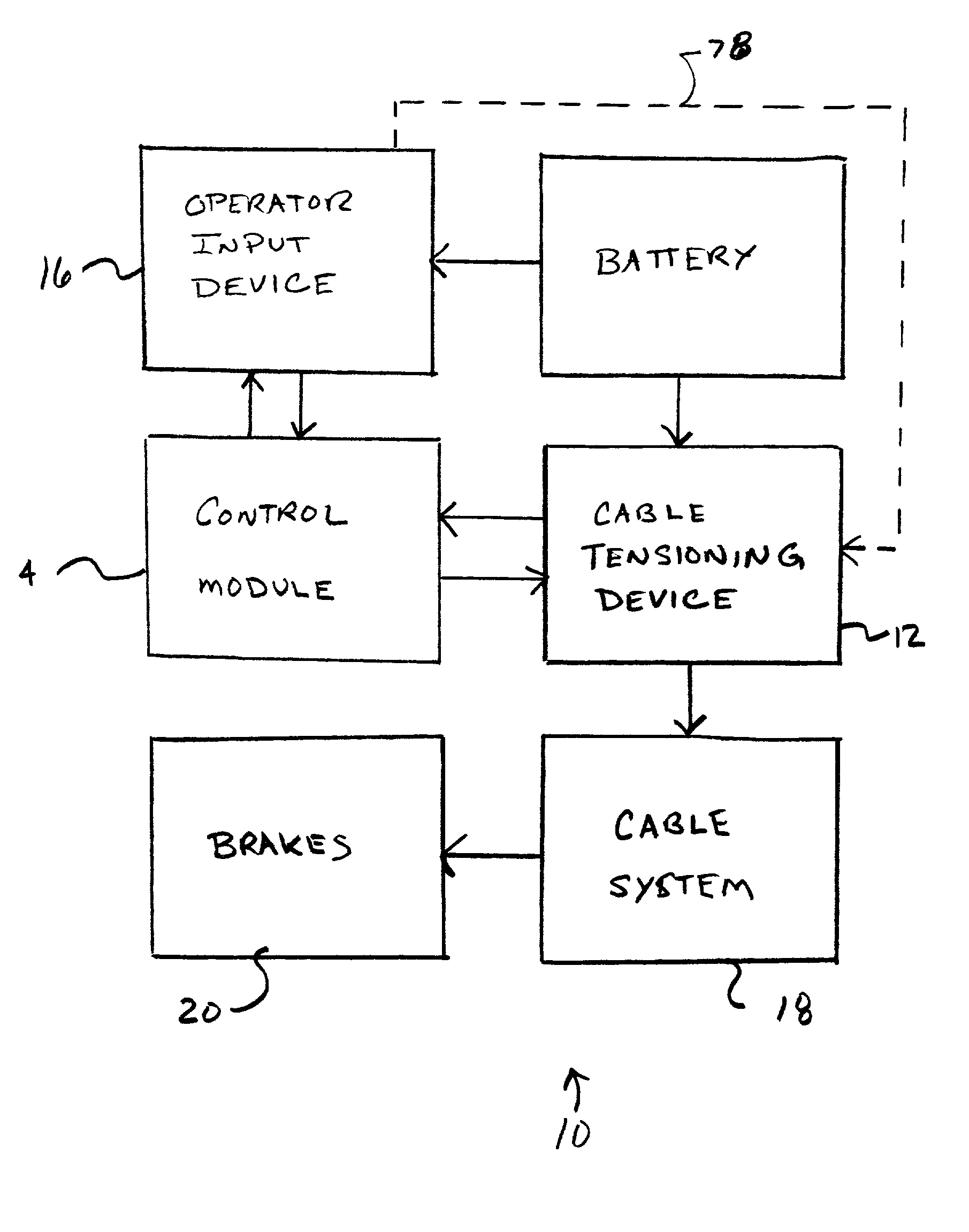
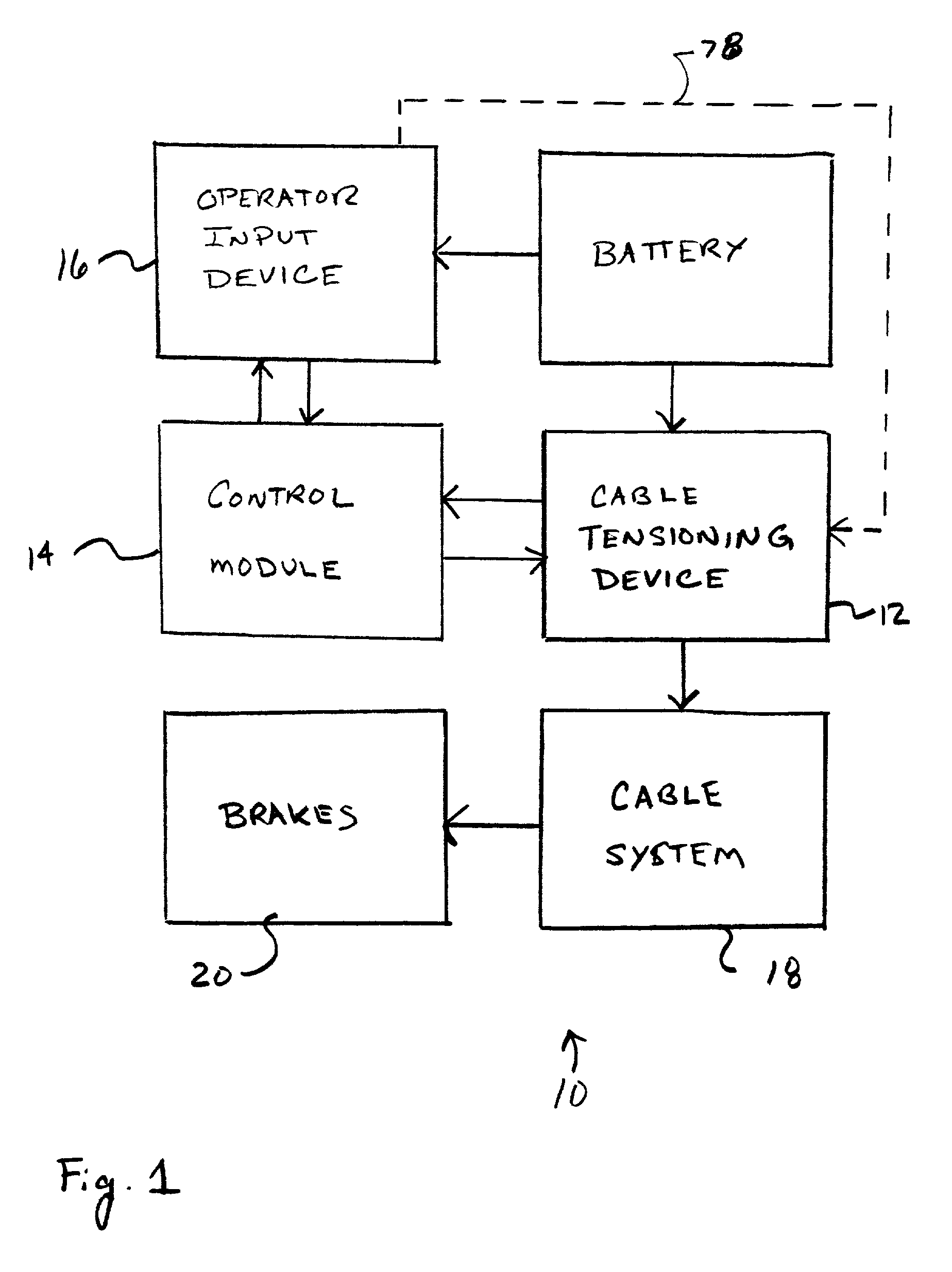
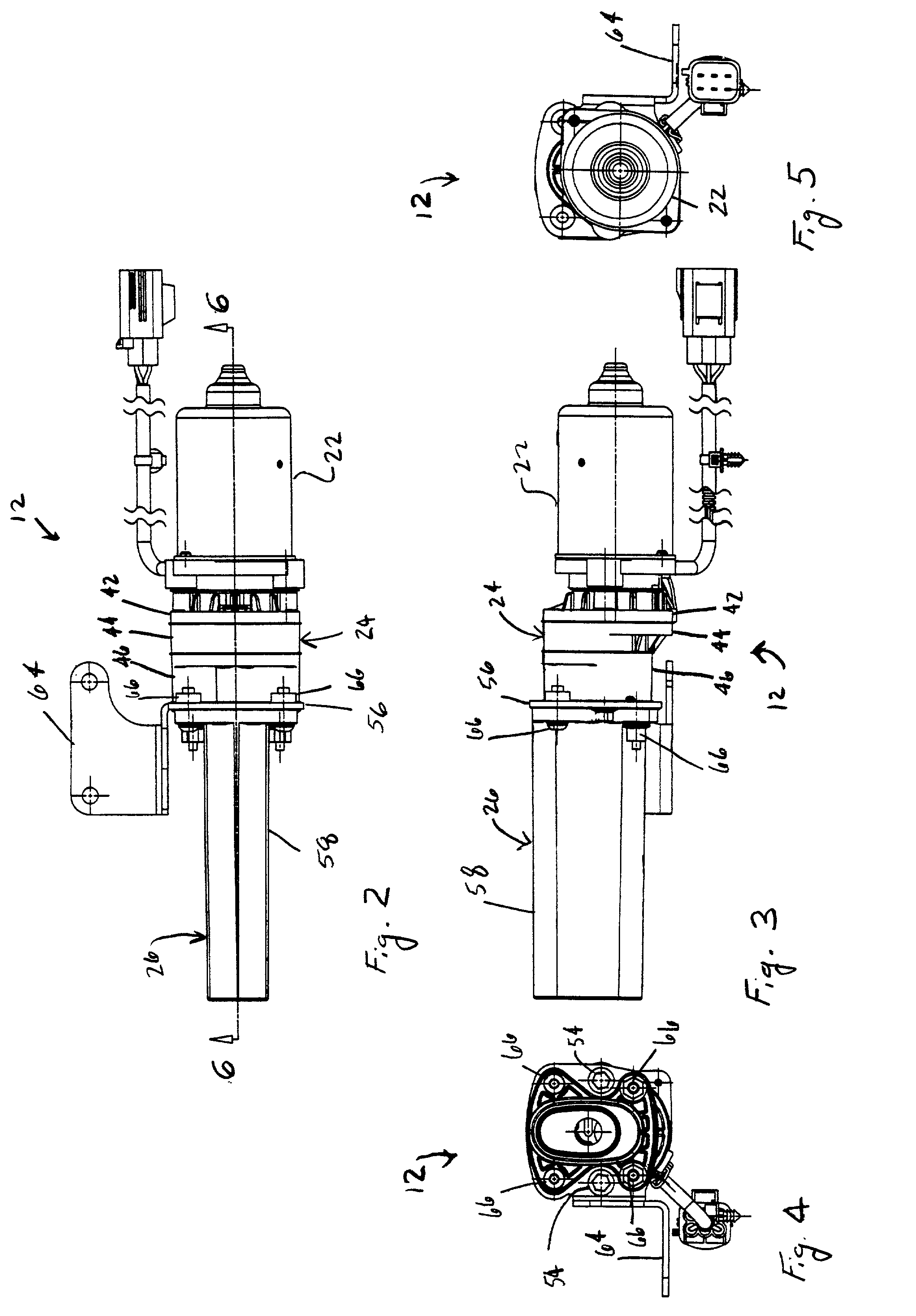
[0024] It will be apparent to those skilled in the art, that is, to those who have knowledge or experience in this area of technology, that many uses and design variations are possible for the improved electrically actuated, motor driven cable tensioning device disclosed herein. The following detailed discussion of various alternative and preferred embodiments will illustrate the general principles of the invention with reference to an electric parking brake (EPB) system for use with a motor vehicle. Other embodiments suitable for other applications will be apparent to those skilled in the art given the benefit of this disclosure.
[0025] The term "snap-fit" connection is used herein and in the claims to mean a connection between at least two components wherein at least one of the components has a protrusion or abutment which engages the other component to form an interlock or interference which retains the components together when they are connected and at least one of the components...
PUM
 Abstract
Description
Claims
Application Information