Solid state heat pump appliance with carbon foam heat sink

Inactive Publication Date: 2005-09-27
GIBLIN PERCY
View PDF10 Cites 26 Cited by
  • Summary
  • Abstract
  • Description
  • Claims
  • Application Information

AI Technical Summary

Benefits of technology

[0027]The above noted objects and other objects of the invention are accomplished by a miniature thermionic personal heating and cooling device for heating or cooling a portion of a user's body that utilizes a porous carbon foam heat sink secured to one surface of a thermionic thermal diode module. The heat sink is formed of a thermally conductive open cell foam medium through which air can pass and is partially enclosed by a shroud and a surrounding air filter. The opposed surface of the thermionic member is secured to a flexible thermal transfer band that is releasably strapped to a portion of the user's body. A miniature air pump and a battery are contained in a small enclosure that is releasably secured on another portion of the user's body remote from the thermal transfer band. A flexible tubular conduit connects the air pump inlet to the shroud and draws ambient air through the thermally conductive open cell foam medium. Electrical leads connected between the battery and the

Problems solved by technology

These types of prior art heat sinks are bulky and heavy and generally constitute the largest component of the heat pump device and thereby render the devices unsatisfactory for applications having size or weight restrictions.
A fan placed in close proximity of the heat sink also adds to the size of the device.
Most of these prior art devices are unsatisfactory for personal cooling applications having size or weight restrictions beca

Method used


Image

  • Solid state heat pump appliance with carbon foam heat sink
  • Solid state heat pump appliance with carbon foam heat sink
  • Solid state heat pump appliance with carbon foam heat sink

Examples


Embodiment Construction

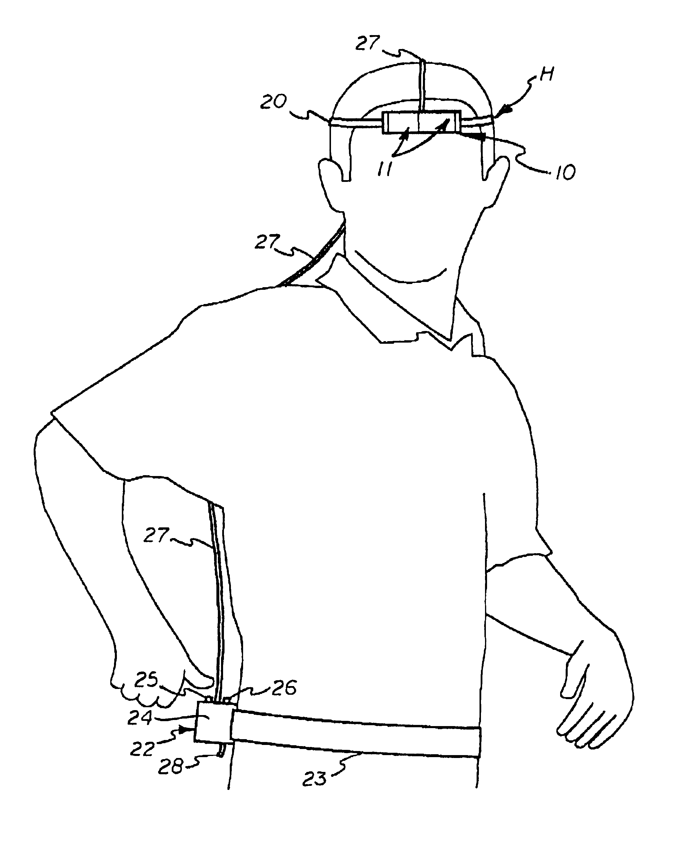
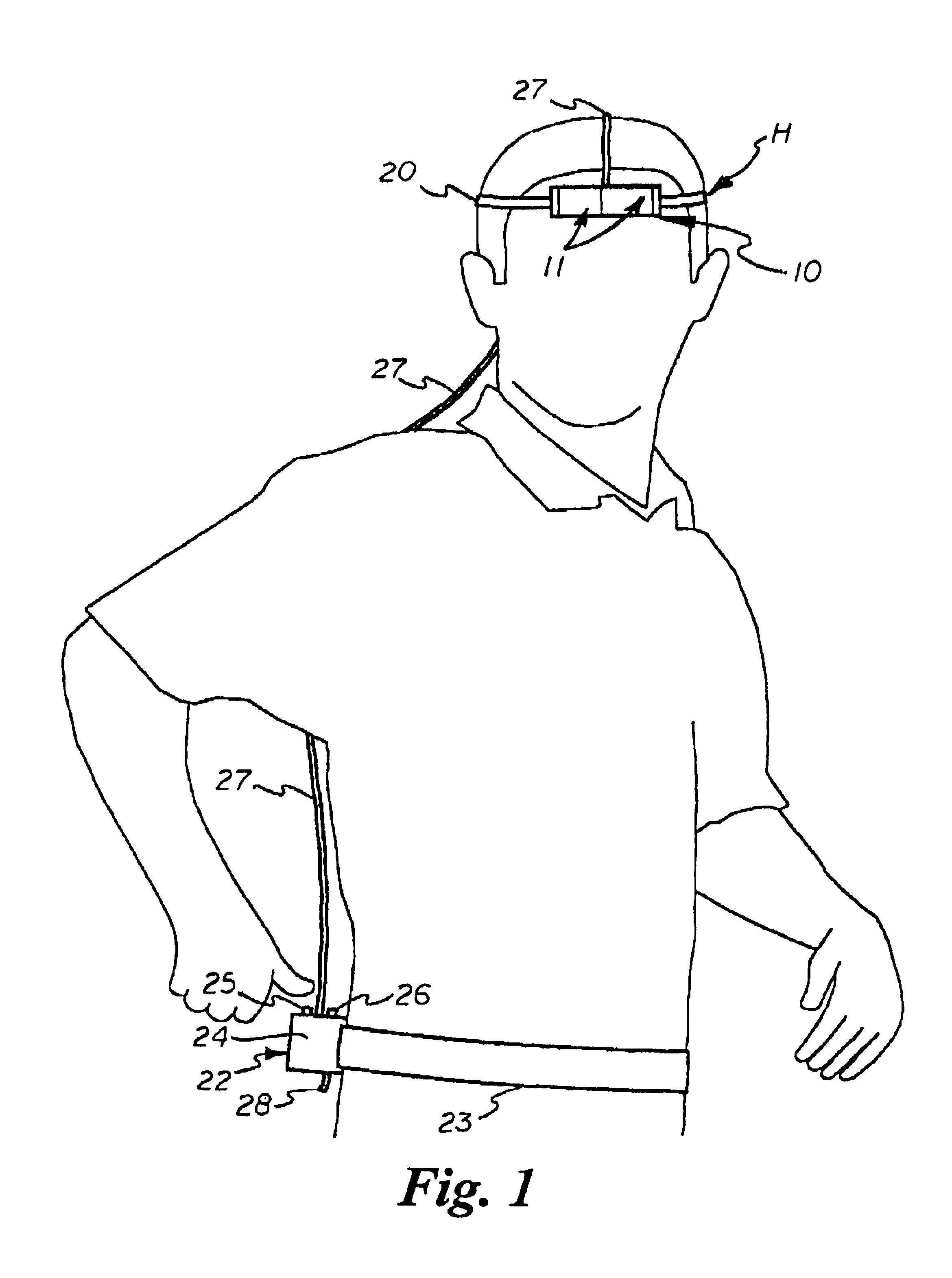
[0034]Referring to the drawings by numerals of reference there is shown in FIG. 1, a headband H worn on the head of a person which incorporates a miniature solid-state thermionic heating and cooling device 10 in accordance with the present invention. The device 10 in the illustrated example utilizes a pair of thermionic thermal diode heating and cooling units 11 (described hereinafter) which are held in place by a securing strap 20 that is releasably fastened around the forehead of the person. It should be understood that the device may utilize one or a plurality of thermionic thermal diode heating and cooling units 11, and may also be worn on other parts of the body, such as on the person's arm or leg.

[0035]An air pump and power supply unit 22 is secured to the person's waist by a belt strap 23. The air pump and power supply unit 22 includes a small enclosure or case 24 that contains a miniature air vacuum pump and a DC battery electrically connected to the air pump motor. A commer...


PUM


Abstract

A thermionic heating and cooling device for heating or cooling a portion of a user's body utilizes thermal diodes having a first surface in thermal contact with a flexible thermal transfer band strapped to a portion of the user's body and a second surface spaced apart therefrom with a thermally conductive porous carbon foam heat sink secured to their second surface which is partially enclosed by a shroud and a surrounding air filter. A small enclosure worn by the user contains an air pump, a battery and a switch. A flexible conduit connects the air pump and shroud and draws ambient air through the porous carbon foam medium. The thermal diodes are connected to the battery by leads extending through the conduit. A voltage bias between the diode surfaces creates a cold surface and hot surface opposite each other and causes electrons to flow in one direction and transfer heat from the first surface to the second and into the heat exchanger, and the heat is prevented from returning to the first surface.

Description

CROSS REFERENCE TO RELATED APPLICATION[0001]This is a continuation-in-part of U.S. application Ser. No. 09 / 950,304 filed Sep. 10, 2001, now U.S. Pat. No. 6,438,964, and priority thereof is claimed.BACKGROUND OF THE INVENTION[0002]1. Field of the Invention[0003]This invention relates generally to solid-state thermionic heating and cooling devices for thermally treating the human body, and more particularly to such a device that has a solidstate thermionic thermal diode unit with a carbon foam heat sink that provides greater surface area per unit volume and significantly greater heat transfer efficiency than conventional thermoelectric Peltier devices with finned heat sinks and facilitates miniaturization.[0004]2. Description of the Related Art[0005]Peltier effect thermoelectric heat pumping devices that are used for thermally treating (cooling or heating) the human body are known in the art. Such solid-state heat pumping devices typically contain a Peltier module, a heat sink and a f...

Claims


Application Information

Patent Timeline
IPC IPC(8): A41D13/005F25B21/02F25B21/04H01L35/00H01L35/28H01L35/30A61F7/00A61F7/02
CPCA41D13/005A42B1/008A61F7/007F25B21/04H01L35/00H01L35/30A61F2007/0001A61F2007/006A61F2007/0075A61F2007/0078A61F2007/0094A61F2007/0228H10N10/00H10N10/13
Inventor GIBLIN, PERCY
Owner GIBLIN PERCY
Why Eureka
Try Eureka