Self tuning RFID tags

a self-tuning and rfid technology, applied in the field of self-tuning rfid tags, can solve the problems of variable impedance of the antenna, and achieve the effects of less power to operate, increase the power that the ic can extract, and improve matching

Active Publication Date: 2016-05-24
IMPINJ
View PDF8 Cites 4 Cited by
  • Summary
  • Abstract
  • Description
  • Claims
  • Application Information

AI Technical Summary

Benefits of technology

[0007]Embodiments are directed to a tuning circuit used to improve the matching between an antenna and an integrated circuit (IC) in an RFID tag, to increase the amount of power that the IC can extract from an incident RF wave. The tuning circuit, which requires less power to operate than the IC itself, adjusts a variable impedance to improve the impedance match between the IC and the tag antenna. The IC may activate when the tag extracts sufficient power from the RF wave or when the tuning circuit finishes its impedance matching.

Problems solved by technology

Unfortunately, antenna impedance may vary with environmental conditions such as humidity, substrate material, dielectric materials near the tag, etc.

Method used


Image

  • Self tuning RFID tags
  • Self tuning RFID tags
  • Self tuning RFID tags

Examples


Embodiment Construction

[0021]In the following detailed description, references are made to the accompanying drawings that form a part hereof, and in which are shown by way of illustration specific embodiments or examples. These embodiments or examples may be combined, other aspects may be utilized, and structural changes may be made without departing from the spirit or scope of the present disclosure. The following detailed description is therefore not to be taken in a limiting sense, and the scope of the present invention is defined by the appended claims and their equivalents.

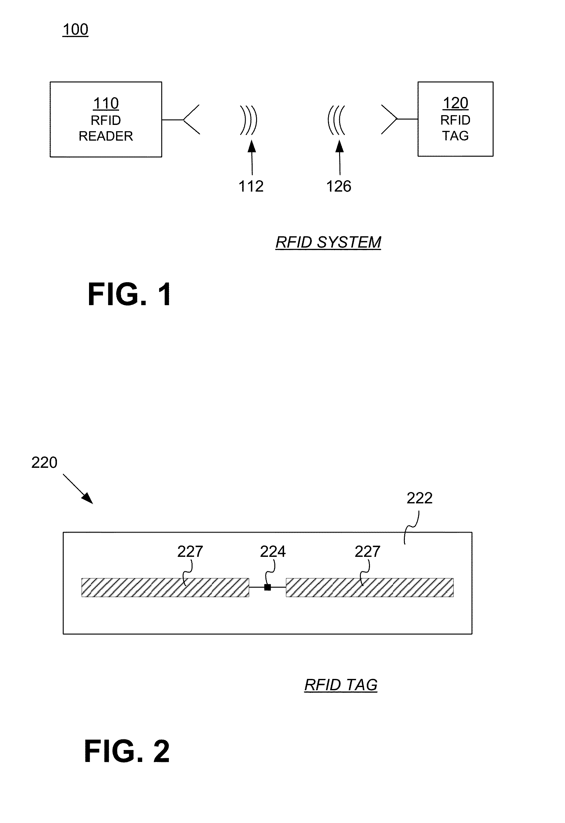
[0022]The following terms may be used herein as follows. The term “IC” is used herein to mean an RFID Integrated Circuit. The term “inlay” is used herein to refer to a substrate including an antenna and optionally a matching network. The term “tag” is used herein to refer to an inlay with an RFID IC coupled to the antenna. The term “sensitivity” is used to mean the minimum RF power for the IC to operate. The term “variable impedanc...


PUM


Abstract

A tuning circuit in an RFID tag may be used to match antenna and integrated circuit (IC) impedances to maximize the efficiency of IC power extraction from an incident RF wave. The tuning circuit, which requires less power to operate than the IC, adjusts a variable impedance to improve the impedance matching between the IC and the tag antenna and thereby increase the IC power extraction efficiency. The IC may begin operating according to a protocol when it extracts sufficient power from the RF wave or when an optimal impedance matching and power transfer is achieved.

Description

CROSS-REFERENCE TO RELATED APPLICATIONS[0001]This application is a continuation under 35 U.S.C §120 of co-pending U.S. patent application Ser. No. 13 / 345,654 filed on Jan. 6, 2012, which claims the benefit under 35 U.S.C §119 (e) of U.S. Provisional Application Ser. No. 61 / 430,949 filed on Jan. 7, 2011. The disclosures of the U.S. Patent application and the provisional patent application are hereby incorporated by reference in their entireties.BACKGROUND[0002]Radio-Frequency Identification (RFID) systems typically include RFID readers, also known as RFID reader / writers or RFID interrogators, and RFID tags. RFID systems can be used in many ways for locating and identifying objects to which the tags are attached. RFID systems are particularly useful in product-related and service-related industries for tracking objects being processed, inventoried, or handled. In such cases, an RFID tag is usually attached to an item or to its package.[0003]RFID techniques include an RFID reader inter...

Claims


Application Information

Patent Timeline
Patent Type & Authority Patents(United States)
IPC IPC(8): H04Q5/22G06K19/07
CPCG06K19/0715G06K19/0709H01Q1/2208H01Q1/248H01Q5/335H03H7/38H04Q2213/13095
Inventor SRINIVAS, SHAILENDRAKUHN, JAYOLIVER, RONALD A.HYDE, JOHN D.DIORIO, CHRISTOPHER J.
Owner IMPINJ
Why Eureka
Try Eureka