Structure of air-packing device having improved shock absorbing capability

a technology of air-packing device and air-packing bag, which is applied in the direction of transportation and packaging, tray containers, packaging goods types, etc., can solve the problems of not being able to recycle styroform, soot is produced, flake or chip comes off, etc., to improve the shock absorption ability and reduce the mechanical shock or vibration of the product

Inactive Publication Date: 2006-02-21
AIR PAQ
View PDF13 Cites 51 Cited by
  • Summary
  • Abstract
  • Description
  • Claims
  • Application Information

AI Technical Summary

Benefits of technology

[0010]It is, therefore, an object of the present invention to provide a structure of an air-packing device for packing a product that can minimize a mechanical shock or vibration to the product when a container box carrying the product is dropped or collided.
[0011]It is another object of the present invention to provide a structure of an air-packing device that can be produced efficiently with low cost and can effectively absorb the impact to the product when the container box carrying the product is dropped or collided.
[0012]It is a further object of the present invention to provide a structure of an air-packing device that can easily form a cushion portion and a container portion for packing the product by a post heat-sealing treatment.
[0013]It is a further object of the present invention to provide a structure of an air-packing device that can easily form a double layer cushion portion and an opening for packing the product by a post heat-sealing treatment.
[0021]According to the present invention, the air-packing device can minimize a mechanical shock or vibration to the product when a container box carrying the product is dropped or collided. The sheet form of the air-packing device is folded and the post heat-seal treatment is applied thereto, thereby creating a structure unique to a production to be protected. The air-packing device can easily form a cushion portion and a container portion for packing the product by a post heat-sealing treatment where the container portion floatingly supports the product in a container box to absorb the shock applied to the container box. The air-packing device having the double layer cushion portion has a further improved shock absorbing capability.

Problems solved by technology

Although the styroform package material has a merit such as a good thermal insulation performance and a light weight, it has also various disadvantages: recycling the styroform is not possible, soot is produced when it burns, a flake or chip comes off when it is snagged because of it's brittleness, an expensive mold is needed for its production, and a relatively large warehouse is necessary to store it.
Third, the air-packing device does not produce a chip or dust which may have adverse effects on precision products.
However, there is an increasing need to store and carry precision products or articles which are sensitive to shocks and impacts often involved in shipment of the products.

Method used


Image

  • Structure of air-packing device having improved shock absorbing capability
  • Structure of air-packing device having improved shock absorbing capability
  • Structure of air-packing device having improved shock absorbing capability

Examples


first embodiment

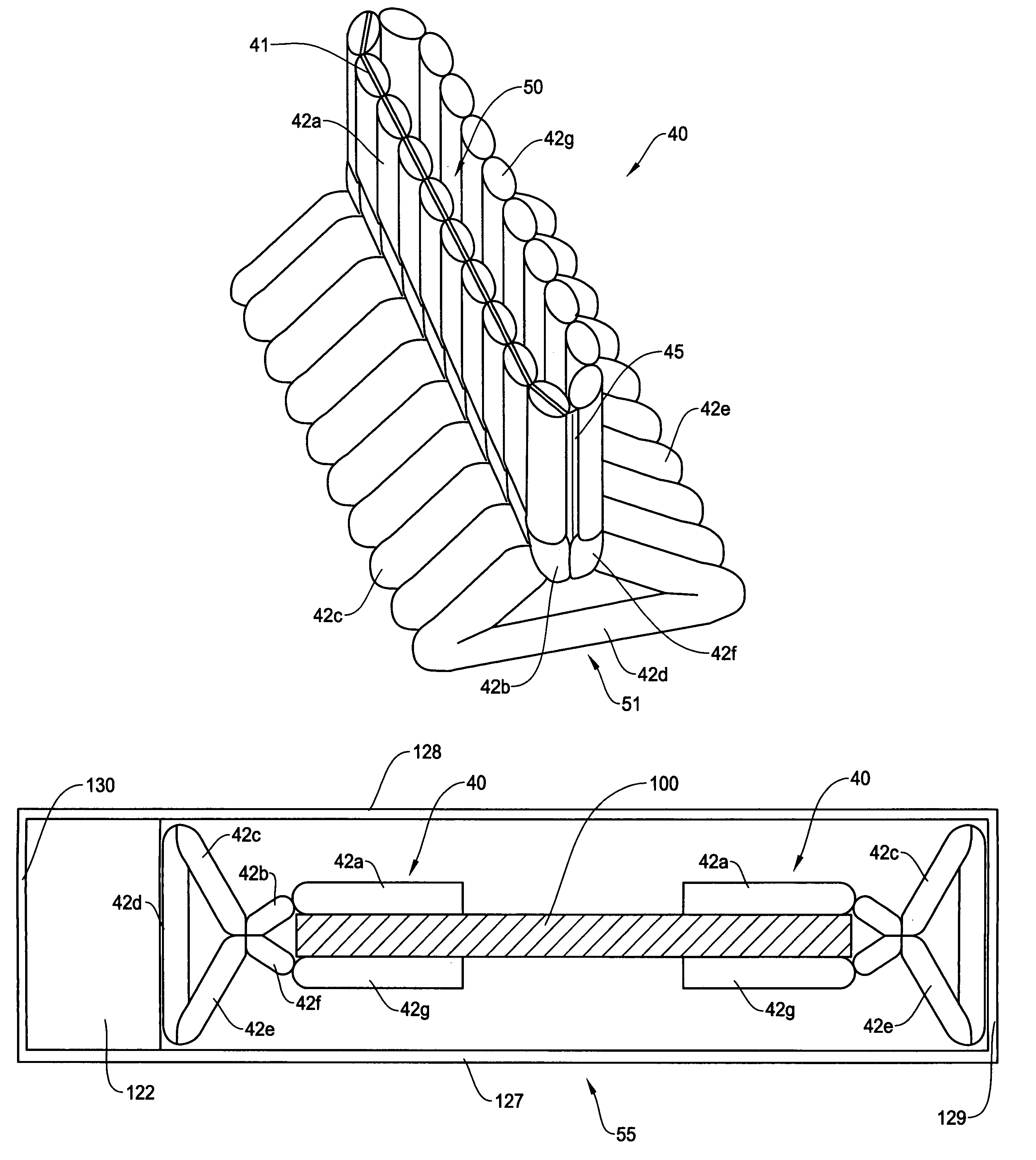
[0049]FIG. 4 is a perspective view showing an air-packing device of the present invention for significantly reducing the shock and impact to the product. The air-packing device of the present invention is made of a plurality of air cells (air containers or air bags) as noted above. A sheet of air-packing device before forming the shape of FIG. 4 is shown in the plan view of FIG. 5. The shape of FIG. 4 is created by folding and heat-sealing (post heat-sealing treatment) the sheet of air-packing device of FIG. 5 before filling the air.

[0050]As shown in FIGS. 4 and 5, the air-packing device 40 has many sets of air cells each having a check valve 44 and series connected air cells 42a–42g. An air input 41 is commonly connected to all of the check valves 44 so that the air is supplied to each set of air cells 42–42g through the check valve 44. The air-packing device 40 also includes heat-seal flanges 45 for forming the opening (container portion) 50 of FIG. 4 by the post heat-sealing trea...

second embodiment

[0088]FIG. 16 is a cross sectional view showing an example of container box 55 in which the air-packing devices 110 in the present invention are incorporated. In this example, two air-packing devices 110 are used to pack a product 400, such as a laptop computer or a DVD driver, at both ends of the product 400 by the container portions 150. The container box 55 has side walls 127–130 to hold the air-packing devices 110 and the product 400 therein.

[0089]The cushion portions 151 contact with the side walls of the container box 55 while the container portions 150 are in the air in a floating manner. Thus, when packed in the container box 55, the product 400 is held by the air-packing devices 110 and is floated within the container box 55 without directly contacting with the container box 55. Because each air cell is filled with air to an optimum pressure, the air-packing devices 110 can support the product 400 as though the product 400 floats in the container box 55. The shapes and size...


PUM


Abstract

An air-packing device has an improved shock absorbing capability to protect a product in a container box. The air-packing device is configured by first and second plastic films which are bonded at predetermined portions thereby creating a plurality of air containers, each of the air containers having a plurality of series connected air cells; a plurality of check valves established at inputs of the corresponding air containers for allowing compressed air to flow in a forward direction; an air input commonly connected to the plurality of check valves; and heat-seal flanges formed on side edges of the air-packing device. Through a post heat-seal treatment, predetermined points on the air containers and the heat-seal flanges are bonded, thereby creating a container portion having an opening for packing a product therein and a cushion portion for supporting the container portion when the air-packing device is inflated by the compressed air.

Description

FIELD OF THE INVENTION[0001]This invention relates to a structure of an air-packing device for use as packing material, and more particularly, to a structure of an air-packing device having an improved shock absorbing capability for protecting a product from a shock or impact occurred in a channel of distribution by allowing flexible movement of the product packed in the air-packing device where the air packing device maintains the product in a substantially floating state therein while absorbing the shock before being applied to the product.BACKGROUND OF THE INVENTION[0002]In a distribution channel such as product shipping, a styroform packing material has been used for a long time for packing commodity and industrial products. Although the styroform package material has a merit such as a good thermal insulation performance and a light weight, it has also various disadvantages: recycling the styroform is not possible, soot is produced when it burns, a flake or chip comes off when i...

Claims


Application Information

Patent Timeline
Patent Type & Authority Patents(United States)
IPC IPC(8): B65D81/02B65D30/00B65D81/05B65D85/30
CPCB65D81/052
Inventor TANAKA, YASUZUMIKOYANAGI, HIDETOSHIYOSHIFUSA, KATSUTOSHI
Owner AIR PAQ
Why Eureka
Try Eureka