Collapsible filter element

a filter element and collapsible technology, applied in the direction of moving filter element filters, filtration separation, separation processes, etc., can solve the problems of affecting the use of bag filters for certain applications, affecting the life of bag filter elements, and affecting the use of bag filters

Inactive Publication Date: 2006-02-21
GERSHENSON CAROL +1
View PDF45 Cites 5 Cited by
  • Summary
  • Abstract
  • Description
  • Claims
  • Application Information

AI Technical Summary

Benefits of technology

[0010]A more specific object of the present invention is to provide a filter element assembly which has at least two cylindrically shaped and concentrically arranged filter sleeves, each connected at one end thereof to an inlet plate, which inlet plate has means to permit entry of liquid t...

Problems solved by technology

One disadvantage of the popular cartridge is that the flow of liquid to be filtered is from the outside of the element to its inner core resulting in dirt or contaminants remaining behind in the housing when the cartridge element is removed from its housing for replacement.
However, this typical arrangement presents a number of severe limitations which inhibits the use of bag filters for certain applications.
These limitations relate to the fact that bag filter vessels are typically larger than cartridge housings, but the bag filter elements provide only a limited active filtration surface area and limited life.
If the contours and shape of the bottom of the bag filter does not exactly coincide with the contours and shape of the retaining basket, filter bags will have a tendency to burst as a result of the large volume of liquid which it contains.
As a result, most bag filter media can not be manufactured from high efficiency filtration media which is usually more delicate than the more coarse filter media typically used in liquid filter bags.
The typical filter bag is also difficult to insert and remove from the vessel as it has no rigid structure other than possibly a retaining ring at the open top end.
Filter bags rarely provide a reliable bypass seal even when constructed with elastomeric sealing members at the open top end.
Because filter bags have a large holding ...

Method used


Image

  • Collapsible filter element
  • Collapsible filter element
  • Collapsible filter element

Examples


Embodiment Construction

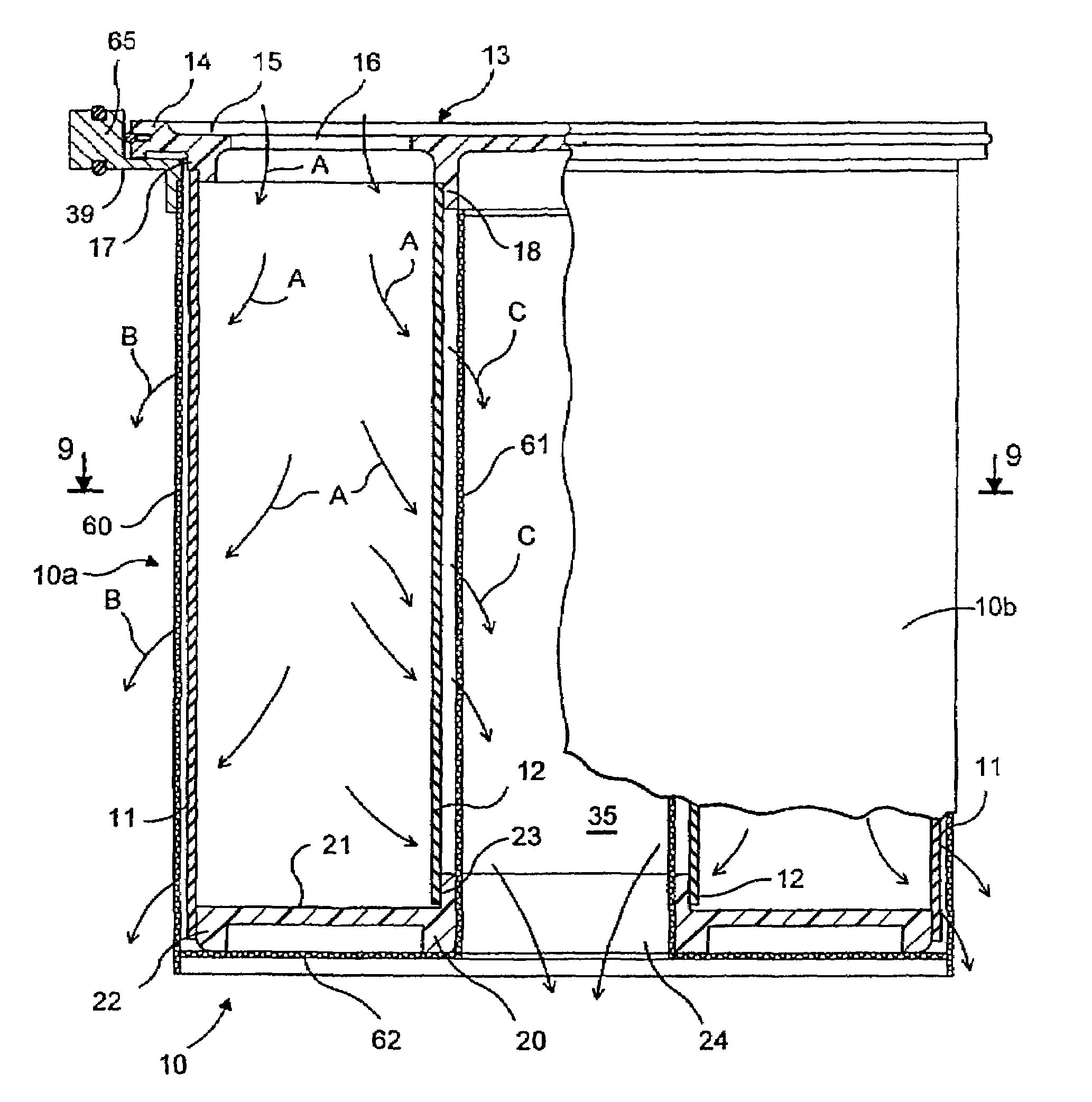
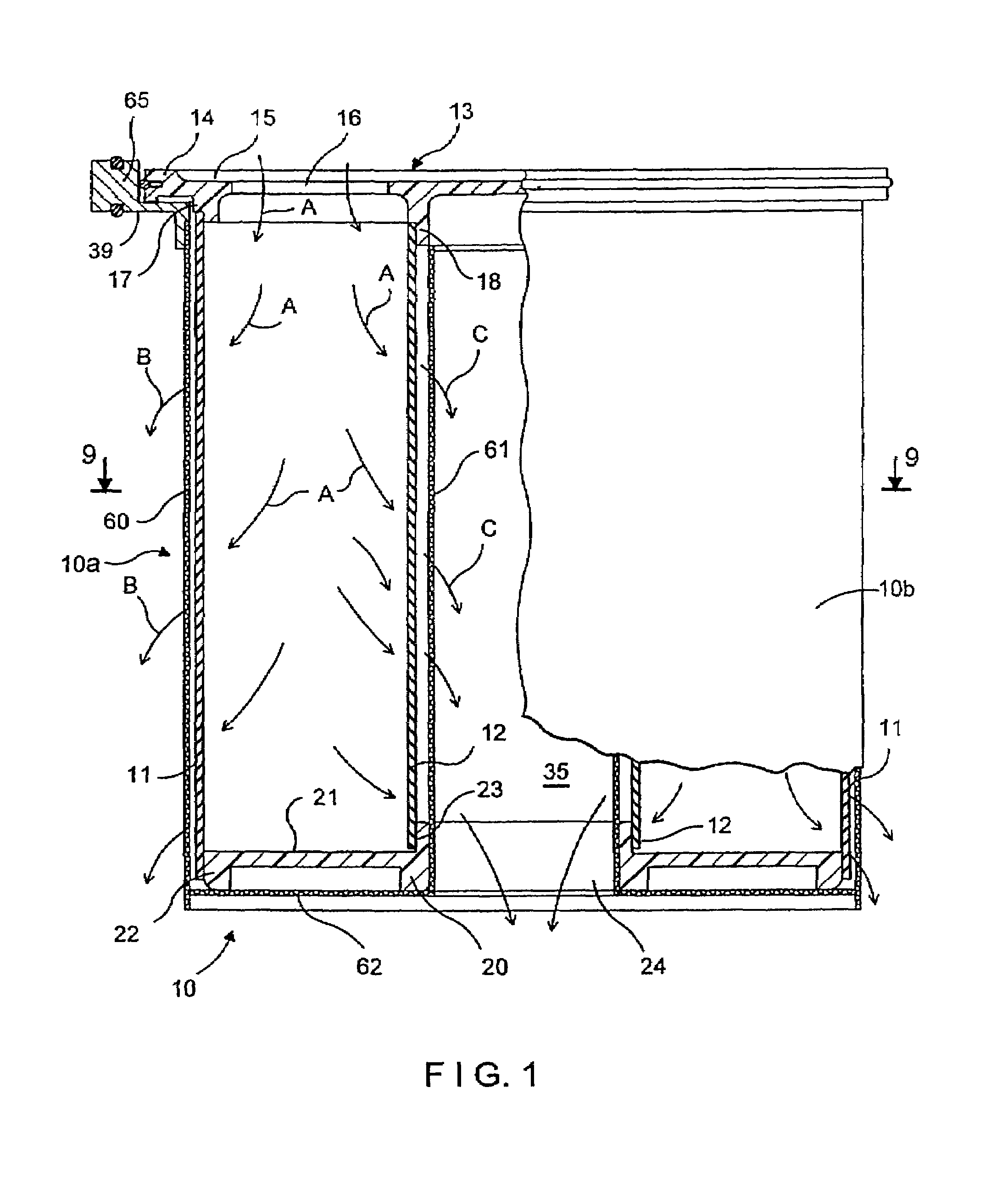
[0031]With reference to FIG. 1, a preferred embodiment of the filter assembly of the present invention is illustrated. Filter 10 of this embodiment includes an annularly shaped support basket 10a and insert or element 10b arrange to be carried by the support basket. Support basket 10a includes a basket flange 65, which is adapted to be supported on a shoulder within a filter housing or vessel, and cylindrically shaped wire mesh screens 60 and 61 which depend from the basket flange 65. Insert 10b has a cylindrical outer sleeve 11 and a cylindrical inner sleeve 12 disposed concentrically within the outer sleeve 11. Outer and inner sleeves 11 and 12 can be made of a variety of porous filter media materials through which liquid to be filtered can pass for filtering out contaminants. Such materials include nylon, polypropylene, needle punched felt and other such similar filter media. The sleeves 11 and 12 are connected at one end to an inlet plate 13 and at the other end to a terminal pl...


PUM

PropertyMeasurementUnit
Forceaaaaaaaaaa
Pressureaaaaaaaaaa
Flow rateaaaaaaaaaa

Abstract

A filter element assembly has at least two cylindrically shaped and concentrically arranged filter media sleeves each connected at one end thereof to an inlet plate and each connected at the other end to a closed end terminal plate. Openings are provided in the inlet plate to permit entry of liquid to be filtered into the annular space between the filter sleeves. The closed end terminal plate prevents flow of unfiltered liquid from the annular space between the sleeves so as to force the liquid through the porous media of the sleeves to effect filtration.

Description

CROSS REFERENCE TO RELATED APPLICATION[0001]This application is a division of application Ser. No. 09 / 864,717 filed May 23, 2001 (now U.S. Pat. No. 6,511,598), which was a continuation-in-part of application Ser. No. 09 / 481,604 filed Jan. 12, 2000 (now U.S. Pat. No. 6,238,560), which was a continuation of application Ser. No. 09 / 115,118 filed Jul. 14, 1998 (now U.S. Pat. No. 6,030,531) which claimed the priority of provisional application Ser. No. 60 / 057,759 filed Sep. 2, 1997, the contents of which is incorporated herein by reference.FIELD OF THE INVENTION[0002]This invention relates generally to the field of liquid filtration devices and more particularly to filter elements and filter element assemblies known as bag filters and cartridge filters. In particular, this invention is directed to a filter element assembly, for use in a bag filter system or in a cartridge filter system, and has at least two concentrically arranged filter media sleeves connected at one end by an inlet end...

Claims


Application Information

Patent Timeline
IPC IPC(8): B01D29/27B01D29/50B01D29/11B01D29/13B01D29/15B01D29/52B01D35/30B01D39/16
CPCB01D29/114B01D29/15B01D29/52B01D35/30B01D39/16B01D29/23B01D29/54B01D29/90B01D29/92B01D29/58B01D29/902B01D29/27B01D2201/34B01D2201/304B01D2201/0446
Inventor GERSHENSON, MOSHE
Owner GERSHENSON CAROL
Why Eureka
Try Eureka