

Heating apparatus for increasing temperature in short period of time with minimum overshoot
a technology of heating apparatus and temperature, which is applied in the direction of electric/magnetic/electromagnetic heating, manufacturing tools, instruments, etc., can solve the problems of low compliance of microscopic images with uneven surfaces of heating rollers, image quality, and uneven toner images on heating targets, etc., to prevent an overshoot of temperature, reduce the effect of machining complexity and high cos
Inactive Publication Date: 2006-02-21
RICOH KK
View PDF19 Cites 44 Cited by
- Summary
- Abstract
- Description
- Claims
- Application Information
AI Technical Summary
Benefits of technology
[0037]As mentioned above, a heating roller, having a core metal covered by an elastic layer (heat-resistant rubber) is available, which prevents gloss unevenness from occurring, and provides a high quality image. However, the elastic layer has poor thermal conductivity, and as many sheets are processed, the surface temperature of the heating roller tends to fall, causing poor fixing. In order to avoid this poor fixing, some image forming apparatuses secure fixing quality by reducing process speed, when the surface temperature of the heating roller becomes lower than a predetermined temperature. Thus, the poor thermal conductivity of the elastic layer of the heating roller works against the speed.
[0048]Another object of the present invention is to provide the heating apparatus, the fixing apparatus, and the image forming apparatus that allow the size of the auxiliary power supply to be small, an installation space to be small, and production costs to be low.
Problems solved by technology
When fluoride system resin as a release agent layer covers the metal core of the heating roller of the fixing apparatus of the heat roller method, since the fluoride system resin is hard, a problem of image quality arises as follows.
The toner image on the heating target has microscopic unevenness.
If the surface of the heating roller is hard, the surface cannot follow the unevenness, and microscopic compliance with the uneven surface of the heating roller becomes low.
While this solution shortens the waiting time of the user, excessive energy is wasted during the standby period.
However, if the power is not supplied to the heating roller during the standby mode in the case of the conventional fixing apparatus, it takes the long time for the temperature of the heating roller to rise at the time of reuse, and the long waiting time reduces user-friendliness.
Thus, expecting a voltage higher than 100 V is not realistic.
However, availability of two separate power line systems is not common.
When a system hangs up, and control of the supply power to the heating element becomes impossible, the probability of ignition becomes considerably high.
If the temperature rise of the heating roller is too quick, the temperature of the heating roller may exceed the ignition temperature of paper before safeguards, such as a temperature fuse and a thermostat, operate.
As mentioned above, conventionally, there is a limit to the amount of the injection energy for raising the temperature of the heating roller in a short time.
However, since it takes several hours to fully charge the rechargeable battery, the problem is that it cannot be used repeatedly in a day.
Further, the rechargeable battery is deteriorated through repeated recharging, the capacity being decreased, and has the nature that the greater is the discharge current, the shorter the service life becomes.
Accordingly, time and effort for battery replacement are required, and operating costs, such as battery costs, become high.
Further, since it takes a long time to charge the rechargeable battery, recharging is often performed at night, with the rechargeable battery being taken out of the apparatus.
Further, the rechargeable battery is capable of discharging little by little, but it has difficulty providing high power for a short duration.
Further, if charging is continued without discharging, gas is generated, causing a failure and being unsafe.
Furthermore, the lead storage battery uses liquid sulfuric acid, which is not desirable for use in an office apparatus.
Due to the shortcomings as described above, it is practically difficult to employ a rechargeable battery for supplying power to the heating element.
Further, according to Japanese Provisional Patent No. 2000-075737, charging a storage battery is carried out externally and during night hours, for charging the storage battery takes a long time.
Since thermal conductivity of the resin is less than metal, the temperature of the film has to be raised before the film is fed into the nip part, otherwise the heat cannot be transmitted to the heating target in the nip part.
For this reason, the area of the plate-like part of the heater becomes large, and high power is required to quickly raise the temperature.
However, in a case that an auxiliary power supply employing a mass capacitor is used, and the fixing roller temperature is controlled by turning on / off the power supply, high power is supplied to the heater, which causes sharp changes of the temperature of the fixing roller, as shown by FIG. 4.
Accordingly, when the temperature of the fixing roller changes in the middle of fixing an image on the heating target, unevenness of image quality develops, and the image quality is degraded.
However, the elastic layer has poor thermal conductivity, and as many sheets are processed, the surface temperature of the heating roller tends to fall, causing poor fixing.
Thus, the poor thermal conductivity of the elastic layer of the heating roller works against the speed.
However, the maximum current of a halogen heater that is usually used for heating of the heating roller is about 10 A through 12 A, and it is difficult to increase the maximum current.
This is because the life of the halogen heater becomes short if a large current is supplied to the halogen heater.
Installing the power supply unit of a high voltage in the apparatus, however, poses the following problems.
Although an access to the inside of the apparatus is in many cases performed by a maintenance person, a power supply terminal may be inadvertently touched during maintenance work, and an electric shock accident may occur.
Further, as the storage capacity of a capacitor cell of the mass capacitor is becoming large, the number of the capacitor cells to be connected in series for obtaining the high voltage and high power is decreasing, and the fewer number of capacitor cells are capable of raising the temperature of the heating target.
At present, since the energy density of the mass capacitor is still low, the size is large, and the cost is still high, it is essential to reduce the number of capacitor cells.
That is, where a halogen heater is employed as the heating element, in order to raise the supply voltage to the halogen heater, capacitor cells capable of providing excess energy are needed, and the power supply for supplying power to the halogen heater becomes large in size and high in cost.
Although the size of the thermistor is quite small and reaction speed is improved, the temperature detecting speed of the thermistor is still low for the configuration where power supplied to the halogen heater is high, and the temperature rises quickly.
Thus, the overshoot of the temperature is another problem to be solved.
Method used
View moreImage
Smart ImageViewing Examples

Examples
embodiment 11
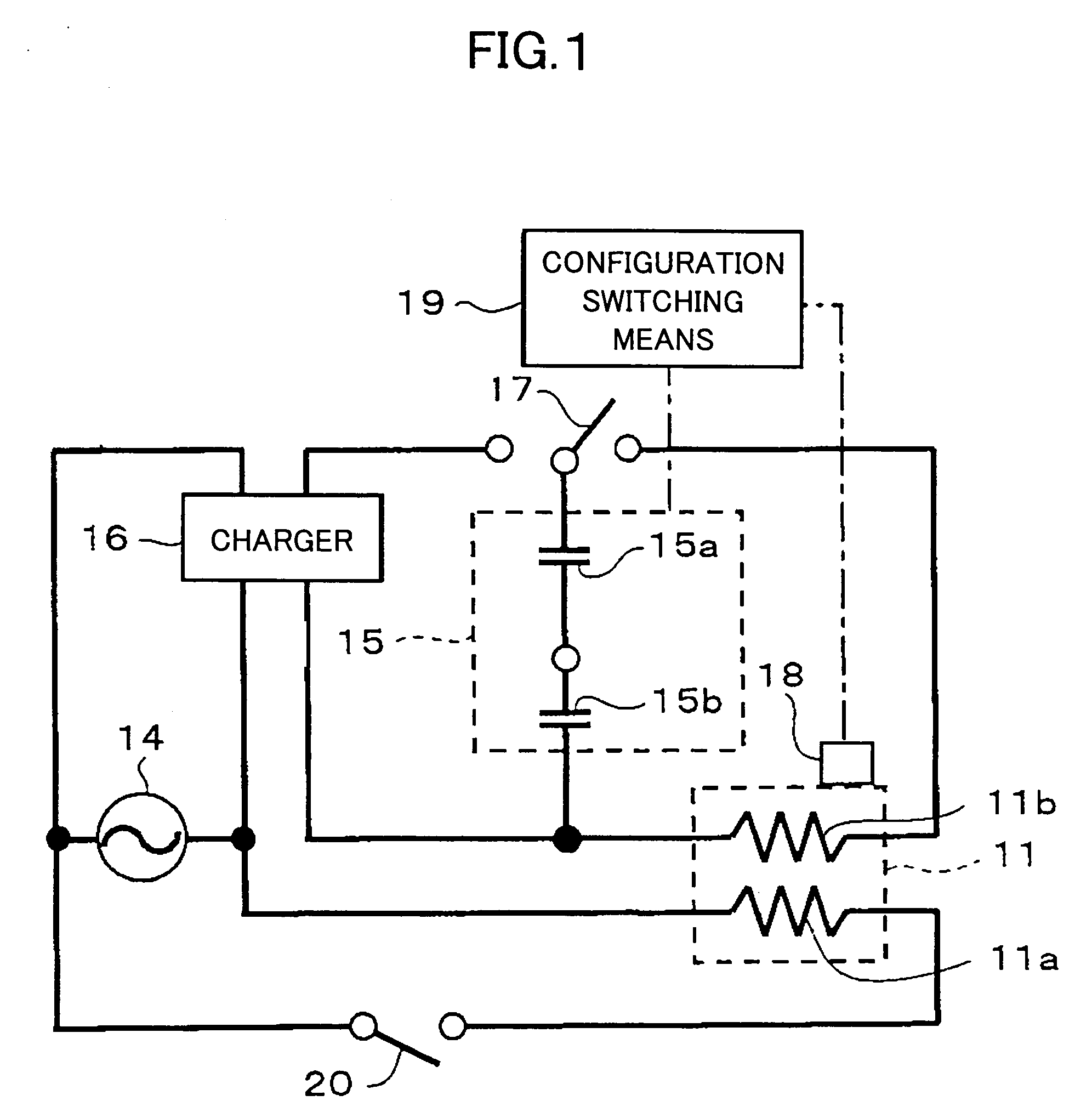
[0073]FIG. 17 is a schematic diagram showing the circuit configuration of the fixing apparatus of the present invention.
embodiment 12
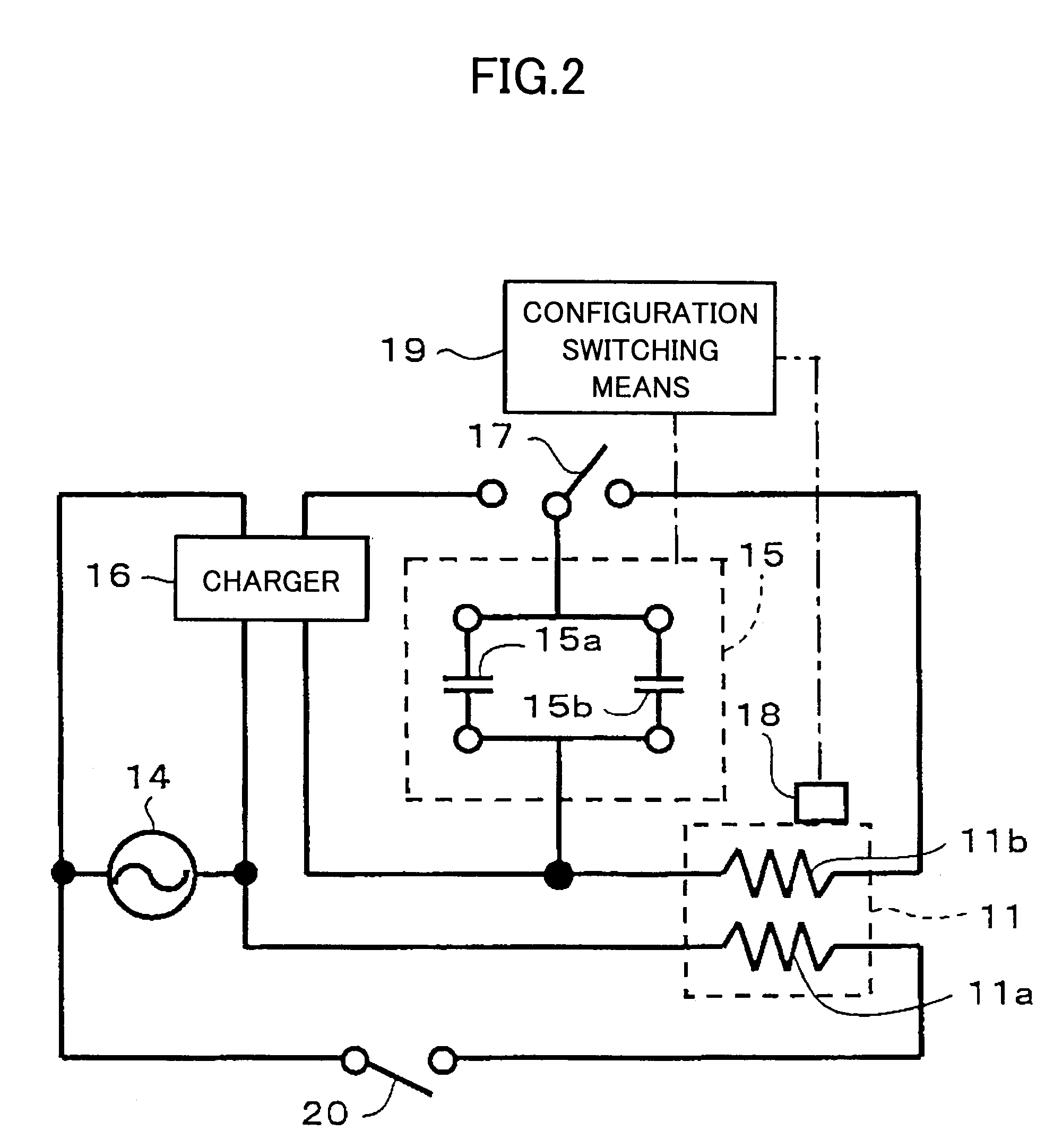
[0074]FIG. 18 is a schematic diagram showing the circuit configuration of the fixing apparatus of the present invention.
embodiment 13
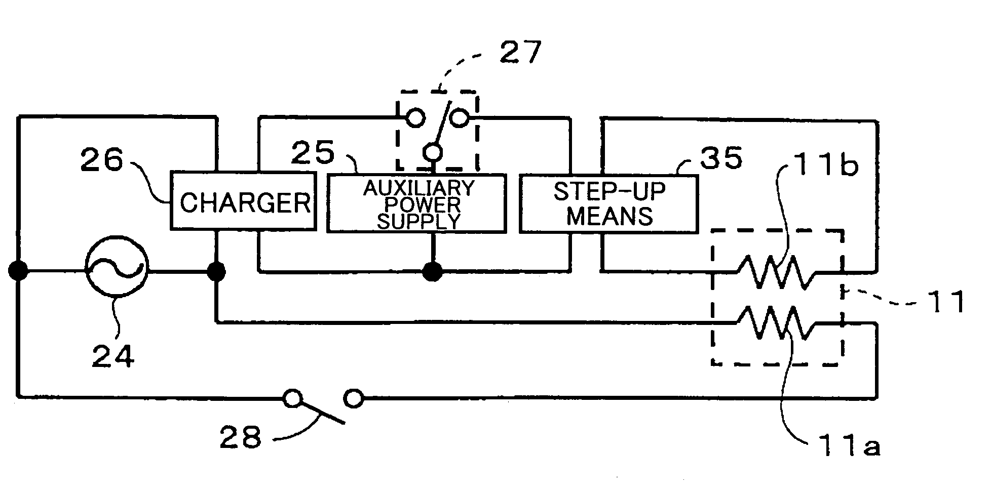
[0075]FIG. 19 is a schematic diagram showing the auxiliary power supply of the present invention.
[0076]FIG. 20 is a table showing experimental values about an influence of an electric current to a human body according to “Electrician's Text” published by The Japan Electric Association.
Login to View More PUM
| Property | Measurement | Unit |
|---|---|---|
| time | aaaaa | aaaaa |
| voltage | aaaaa | aaaaa |
| total power | aaaaa | aaaaa |
Abstract
A heating apparatus includes a heating roller that is heated by heating units, a main power supply that supplies power from an external power supply to the main heating unitl, and an auxiliary power supply that supplies power to the auxiliary heating unit. The auxiliary power supply further includes a mass capacitor of multiple capacitor cells, which are charged by the external power supply. The connection mode of the capacitor cells is changed at least at the time of electric discharge.
Description
BACKGROUND OF THE INVENTION[0001]1. Field of the Invention[0002]The present invention relates to heating apparatuses for heating various targets, such as paper and a film; fixing apparatuses; image forming apparatuses, such as a copying apparatus, a printer, and a facsimile apparatus.[0003]2. Description of the Related Art[0004]Image forming apparatuses, such as a copying apparatus, a printer, and a facsimile apparatus, include a process for forming an image on a heating target, such as a sheet of regular paper and OHP paper. In such image forming apparatuses, although various image formation methods are employed, an electro-photographic method is widely adopted from viewpoints of speed, image quality, cost, and so on.[0005]In the electro-photographic method, a toner image that is to be fixed is formed on the heating target, such as a sheet of regular paper and OHP paper, and a fixing process fixes the toner image on the heating target by heat and pressure applied by a fixing appara...
Claims
Login to View More Application Information
Patent Timeline
 Patent Type & AuthorityPatents(United States)
IPC IPC(8): H05B3/02G03G15/20
CPCG03G15/2039G03G2215/20G03G15/80
InventorKISHI, KAZUHITOKONNO, ERIKO
OwnerRICOH KK