Digital control apparatus for a switching DC-DC converter

a digital control and converter technology, applied in the direction of power conversion systems, electric variable regulation, instruments, etc., can solve the problems of the main disadvantage of the digital control device, the supply voltage of the load, etc., and achieve the effect of lowering the further excursion of the output voltag

Active Publication Date: 2006-02-21
STMICROELECTRONICS SRL
View PDF6 Cites 15 Cited by
  • Summary
  • Abstract
  • Description
  • Claims
  • Application Information

AI Technical Summary

Benefits of technology

[0009]In view of the state of the art described, it is an object of the present invention to provide a digital control apparatus for a

Problems solved by technology

However, the digital control devices have a main disadvantage due to the time delay in the control loop needed for processing the information.
For this reason the digital control devices that are now present in commerce do not assu

Method used


Image

  • Digital control apparatus for a switching DC-DC converter
  • Digital control apparatus for a switching DC-DC converter
  • Digital control apparatus for a switching DC-DC converter

Examples


Embodiment Construction

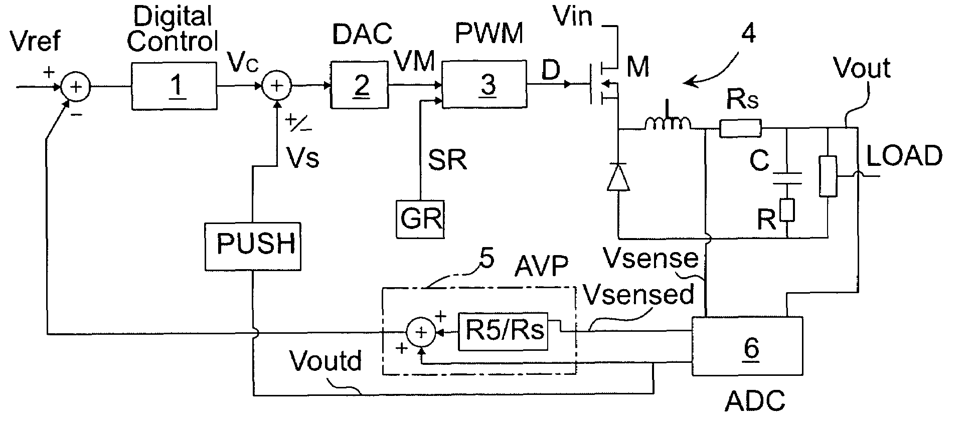
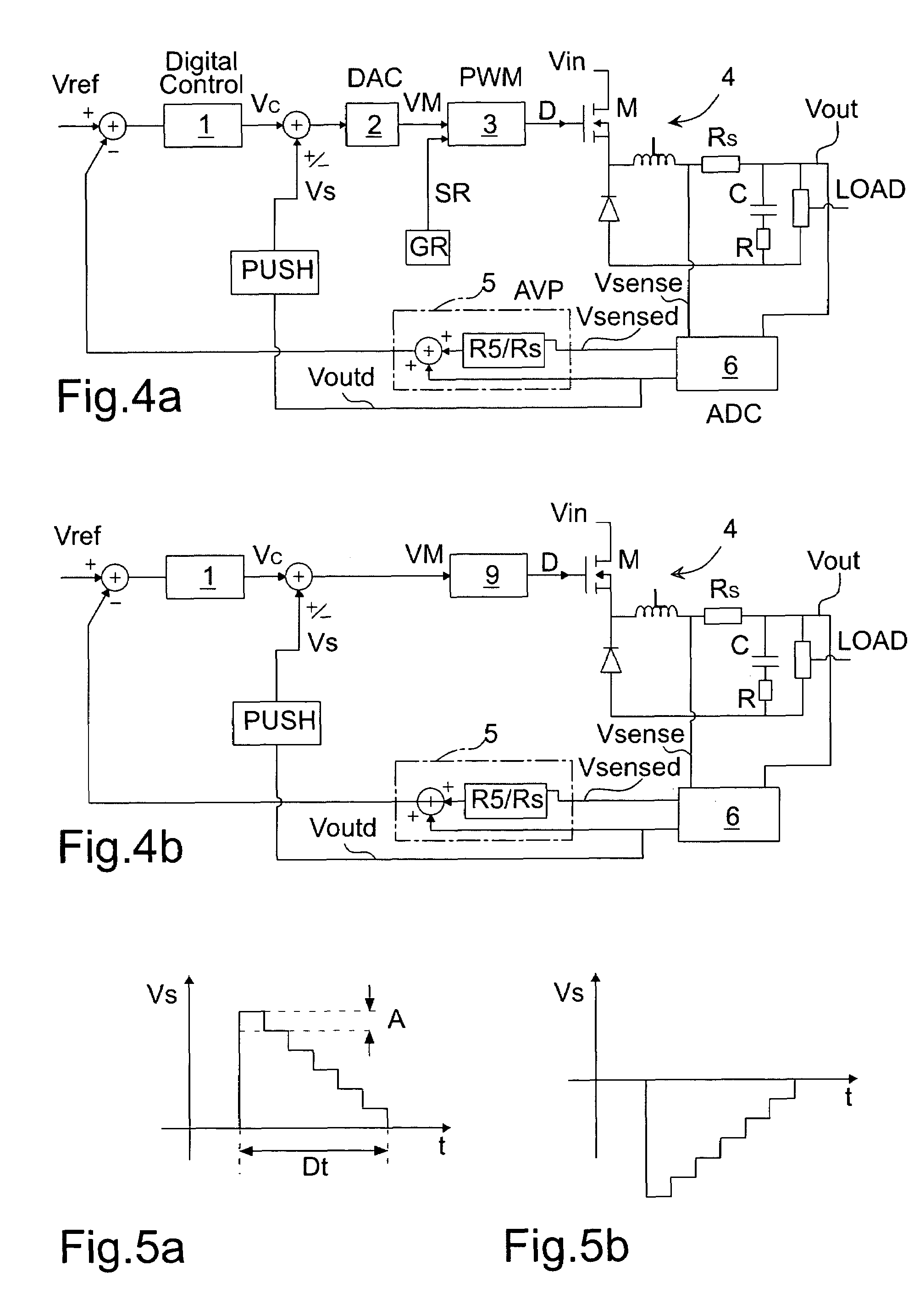
[0021]In FIG. 4a a block scheme of a digital control apparatus for a DC-DC converter according to a first embodiment of the present invention is shown. A digital control block 1 receives an input reference voltage Vref, that is a constant digital signal, and provides an output voltage Vc. The digital control block 1 is preferably performed by means of a PID.

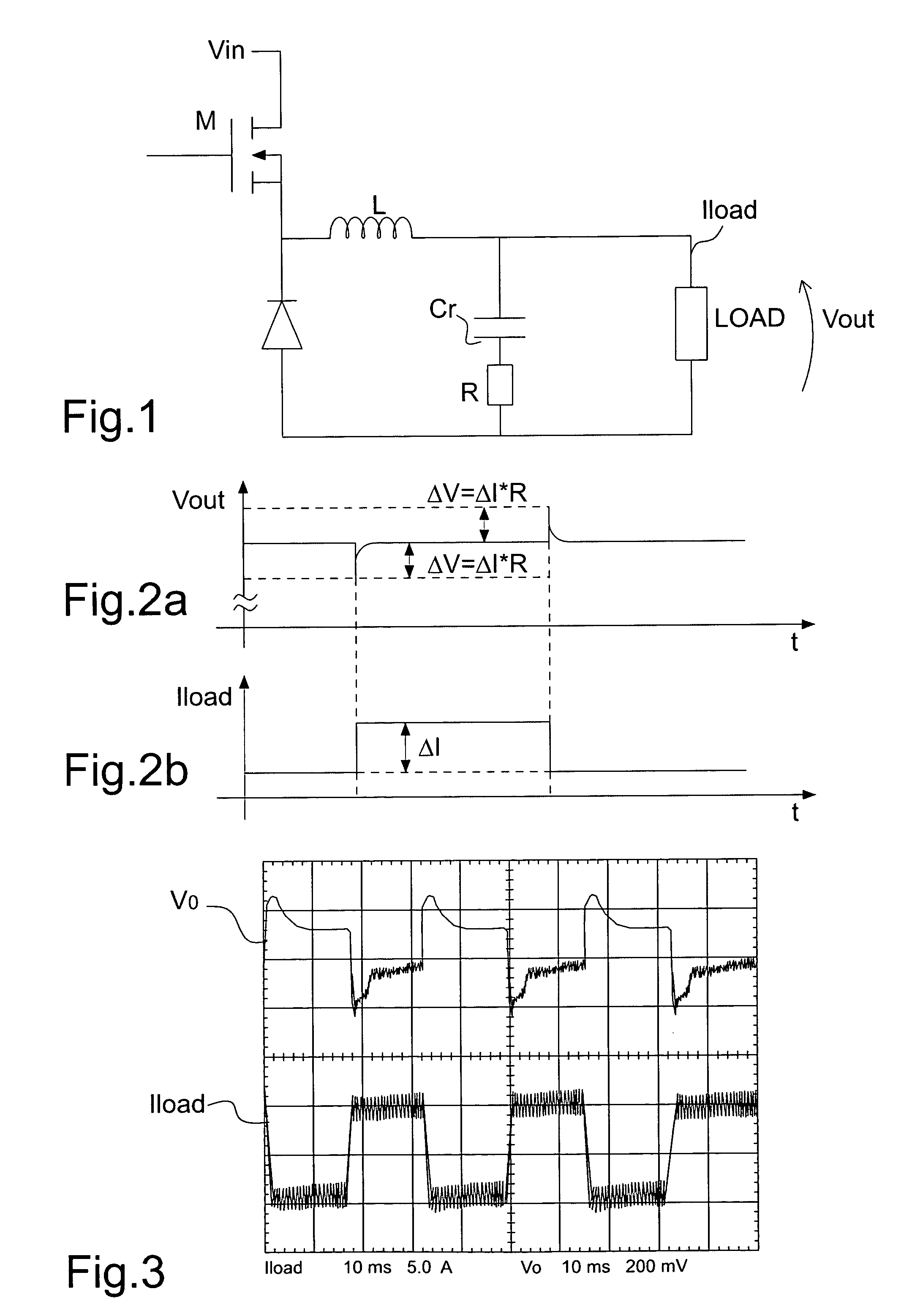
[0022]The signal Vc is sent in input to a digital / analog converter 2 providing the correspondent output analog signal. The last signal and a slope signal SR generated by a device GR are in input to an analog PWM device 3 able to provide a signal D to drive the power transistor M belonging to a DC-DC converter 4, for example the converter shown in FIG. 1.

[0023]The output signal Vout of the converter 4 is sent in input to a analog / digital converter 6; the digital signal Voutd is sent to a block PUSH able to provide a digital signal Vs that is added to or subtracted from the signal Vc in order to carry out a non-linear modulation of...


PUM


Abstract

A digital control apparatus for a switching DC-DC converter includes at least one power transistor and is able to provide a regulated output voltage on a load. The apparatus includes digital control having a reference digital input signal and provides a modulating signal to a PWM device to which is input the modulating signal and which provides an output square wave signal for driving the power transistor of the DC-DC converter such that there is non-linear modulation only when the value of a signal on the load is lower or higher than a prefixed value range.

Description

FIELD OF THE INVENTION[0001]The present invention refers to a digital control apparatus for a switching DC-DC converter.BACKGROUND OF THE INVENTION[0002]There is presently a continuous evolution of computers and above all of microprocessors. The need to process an always greater quantity of information in the shortest possible time has brought to manufacture high performance microprocessors that require high currents (which have a value of tens of amperes) for operation thereof. For this reason devices able to provide a low supply voltage and a high current have been manufactured.[0003]However, the present microprocessors do not require high currents in continuous way but only in prefixed time periods; this is due to the quantity of operations that must be performed in said time periods. Therefore the value of the current adsorbed from them must change from tens of milliamperes to 80–100 amperes in a short time (a few nanoseconds).[0004]Said devices are power supplies comprising swi...

Claims


Application Information

Patent Timeline
IPC IPC(8): G05F1/40H02M3/157
CPCH02M3/157
Inventor MARINO, FILIPPOMINIERI, MARCOCOSTANZA, PIETRO
Owner STMICROELECTRONICS SRL
Why Eureka
Try Eureka