External liquid loop heat exchanger for an electronic system

a technology of electronic systems and liquid loops, applied in the direction of cooling/ventilation/heating modifications, power cables, cables, etc., can solve the problems of compact electronic systems and devices, electronic equipment contained within enclosures generate a significant amount of heat, and may cause thermal damage to electronic equipmen

Active Publication Date: 2006-02-21
HEWLETT-PACKARD ENTERPRISE DEV LP
View PDF21 Cites 101 Cited by
  • Summary
  • Abstract
  • Description
  • Claims
  • Application Information

AI Technical Summary

Problems solved by technology

Electronic equipment contained within the enclosure generates a significant amount of heat.
Thermal damage may occur to the electronic equipment unless the heat is removed.
Compact electronic systems and devices, for example compact computer servers with a rack-mount 1U form factor, typically have very little space available for implementing a cooling capability.
Given the restriction on heat sink height dictated by the form factor and the practical limits on heat sink footprint, cooling capabilities are highly restricted.

Method used


Image

  • External liquid loop heat exchanger for an electronic system
  • External liquid loop heat exchanger for an electronic system
  • External liquid loop heat exchanger for an electronic system

Examples


Embodiment Construction

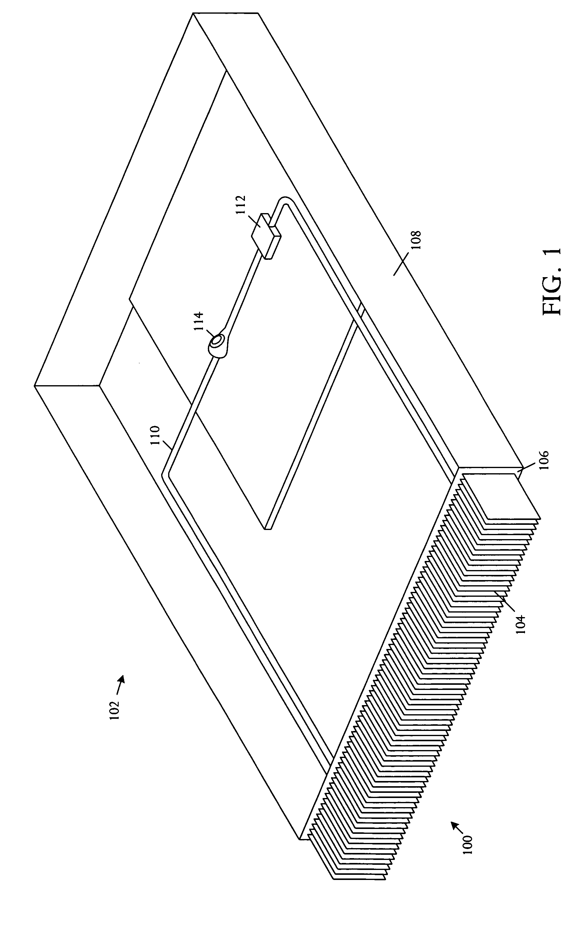
[0012]Referring to FIG. 1, a perspective pictorial diagram depicts a cooling apparatus 100 for usage in an electronic system 102 comprises a liquid loop heat exchanger body 104 is configured for attachment to an exterior surface 106 of an electronic system chassis 108.

[0013]The cooling apparatus 100 may further include a tube 110 capable of enclosing a cooling fluid. The tube 110 extends in a loop that passes interiorly though the heat exchanger body 104 external to the electronic system chassis 108 and also passes into the chassis 108 to cooling plates 112 coupled to electronic components interior to the electronic system chassis 108. The cooling apparatus 100 may also have a pump 114 coupled into the tube 110 that is capable of generating a pressure head suitable to drive the cooling fluid interior to the tube 110 through the loop interior and exterior of the chassis 108.

[0014]Electronic system architectures such as server architectures with a compact form factor may include the l...


PUM


Abstract

A cooling apparatus for usage in an electronic system, a liquid loop heat exchanger body is configured for attachment to an exterior surface of an electronic system chassis.

Description

BACKGROUND OF THE INVENTION[0001]Electronic systems and equipment such as computer systems, network interfaces, storage systems, and telecommunications equipment are commonly enclosed within a chassis, cabinet or housing for support, physical security, and efficient usage of space. Electronic equipment contained within the enclosure generates a significant amount of heat. Thermal damage may occur to the electronic equipment unless the heat is removed.[0002]Compact electronic systems and devices, for example compact computer servers with a rack-mount 1U form factor, typically have very little space available for implementing a cooling capability. Conventional air-cooled heat sinks generally must be directly connected to the heat source. The footprint of the heat sink cannot be much larger than the heat source given the intrinsic heat spreading resistance of an aluminum or copper heat sink. Given the restriction on heat sink height dictated by the form factor and the practical limits ...

Claims


Application Information

Patent Timeline
Patent Type & Authority Patents(United States)
IPC IPC(8): H05K7/20
CPCH05K7/20772H05K7/20727
Inventor MALONE, CHRISTOPHER G.SIMON, GLENN C.
Owner HEWLETT-PACKARD ENTERPRISE DEV LP
Why Eureka
Try Eureka