Zero data loss network protection

a network protection and data loss technology, applied in the field of optical communications, can solve problems such as a certain amount of delay and typically a significant delay with resp

Inactive Publication Date: 2006-02-21
OPTIC153 LLC
View PDF15 Cites 7 Cited by
  • Summary
  • Abstract
  • Description
  • Claims
  • Application Information

AI Technical Summary

Problems solved by technology

The process of detecting the fault, communicating the existence of the fault and switching to a protection route results in a certain amount of delay between the detection of the fault and the re-routing of the data.
Although optical switches have fairly fast response times, resulting in relatively short switch times TSW1 and TSW2, there is typically a significant delay with respect to the times TC2NMS and TC3NMS for the NMS 20 to communicate the switches to the LTEs.

Method used


Image

  • Zero data loss network protection
  • Zero data loss network protection
  • Zero data loss network protection

Examples


Embodiment Construction

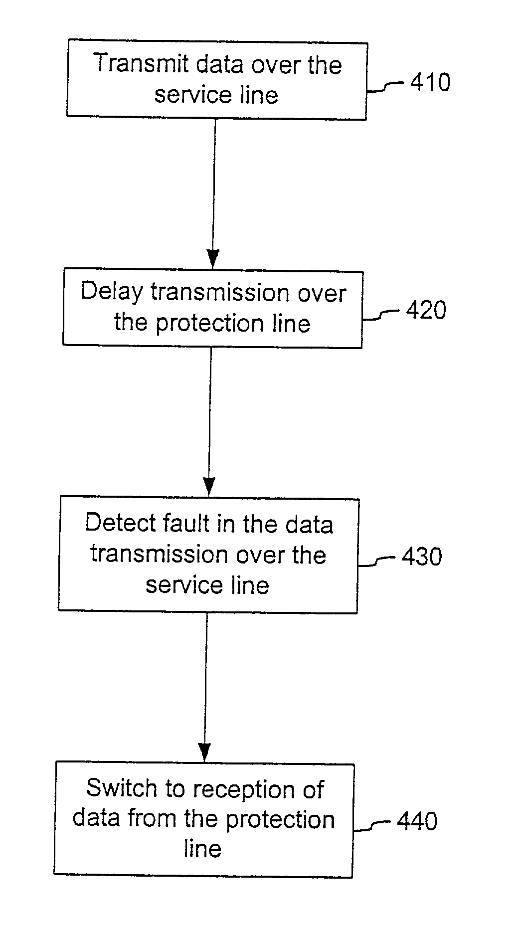
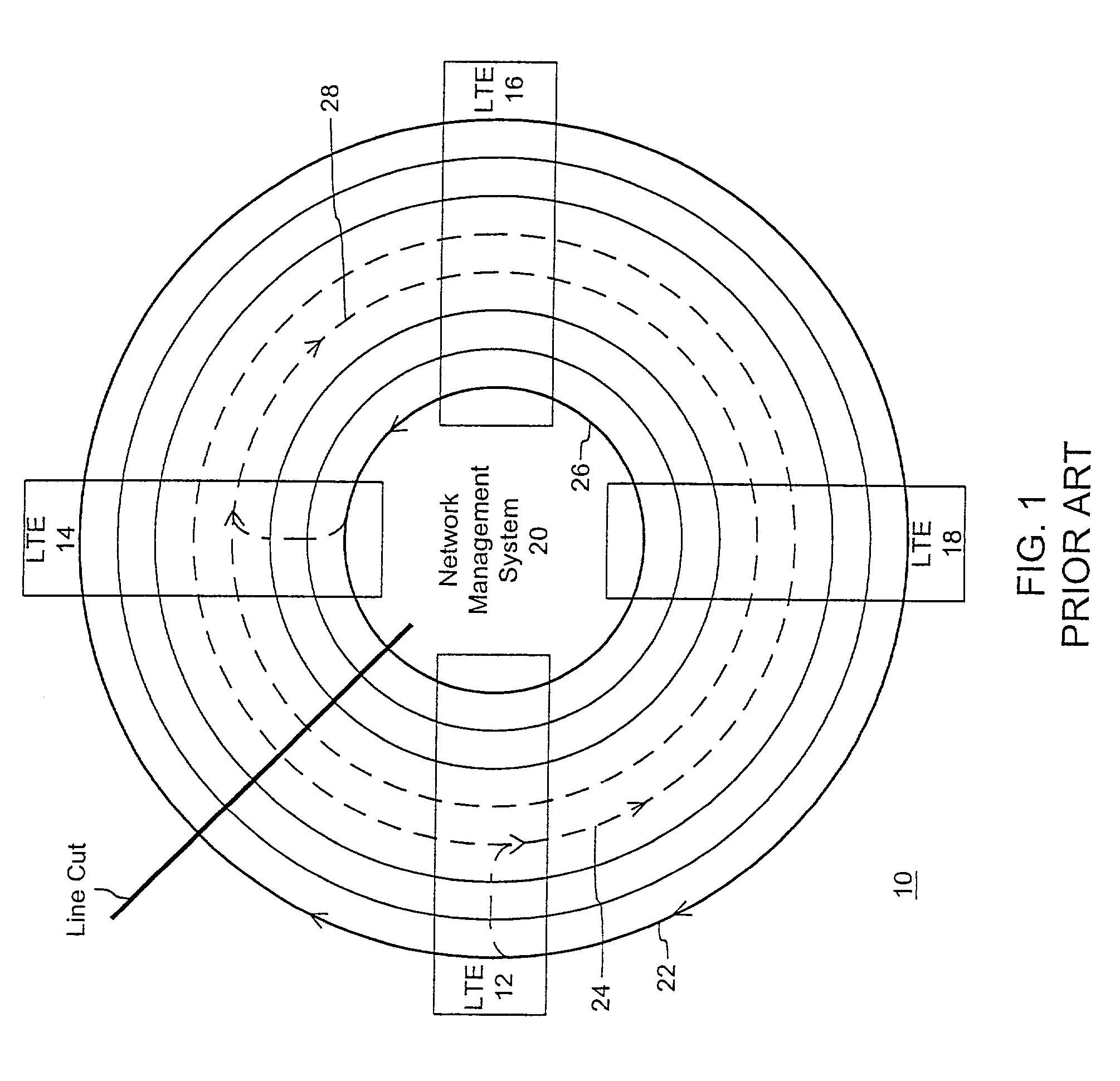
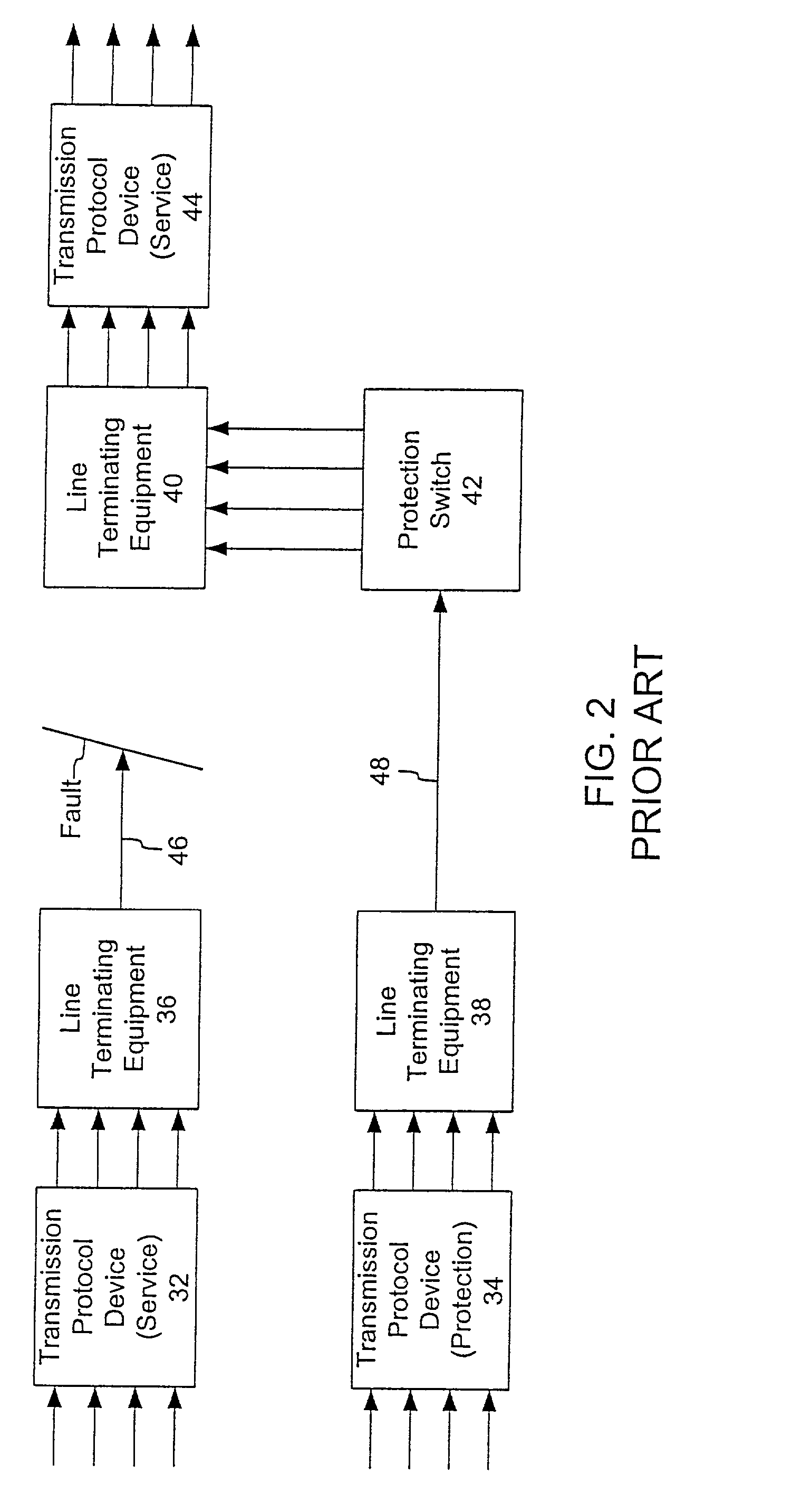
[0021]FIG. 3 is a block diagram of a zero data loss network protection system consistent with the present invention. Like the architecture of FIG. 2, the system of FIG. 3 includes transmission protocol devices 32, 34 and 44, line terminal equipment (LTF) 36, 38 and 40, a protection switch 42, a service line 46 and a protection line 48. The devices 32, 34 and 44 may be implemented as SONET and SDH boxes or an IP router. Alternatively the devices 32, 34 and 44 may be implemented using Multi-Protocol Data Label Switching (MPLS), General MPLS (GMPLS) or other networking schemes. The architecture of FIG. 3 illustrates a 1+1 configuration that provides for the simultaneous transmission of data through the service line 46 and the protection line 48. The zero data loss network protection system is equally applicable to other optical architectures, such as the ring architecture of FIG. 1 or a collapsed ring architecture.

[0022]As described above, when a fault is detected on a service path, da...


PUM


Abstract

A system and method for protecting from the loss of data in an optical data network includes receiving the data over a service optical fiber line, delaying reception of the data over a protection optical fiber line by a first delay amount with respect to the reception of the data over the service optical fiber line, and detecting a fault condition in the service optical fiber line. In response to the detection of the fault condition, the transmission of data over the protection optical fiber line is received. The first delay amount corresponds to at least the amount of time to switch to the reception of the data over the protection optical fiber line from the reception of the data over the service optical fiber line after the detection of the fault condition.

Description

FIELD OF THE INVENTION[0001]The present invention relates generally to optical communications, and more particularly to a system and method for protecting the loss of data in an optical communication system when a fault occurs.BACKGROUND OF THE INVENTION[0002]Current network architectures are configured to allow optimal transmission of binary data in the digital and optical domain. Network users typically require varying degrees of protection for the transmission of the data depending on the applications being used by the particular network user. For example, some users may not need any protection for low priority data applications, and therefore can withstand multiple interruptions for extended periods of time. Other users, however, may be using high priority data applications that require immediate protection of the data traveling over a service optical fiber line.[0003]Protection for data traveling over the service optical fiber line, i.e., service data, may be achieved by altern...

Claims


Application Information

Patent Timeline
Patent Type & Authority Patents(United States)
IPC IPC(8): H04B10/08H04J3/14H04B10/00H04B10/02
CPCH04B10/032H04B10/0791H04J14/0291H04J14/0283
Inventor HAGOPIAN, JOHNFEINBERG, LEE DANIELRAU, JR., WALTER A.
Owner OPTIC153 LLC
Why Eureka
Try Eureka