Resonance frequency correction method and vibration speaker

a frequency correction and frequency correction technology, applied in the field of vibration speakers, can solve the problems of inability to make a perfectly uniform steel plate, inability to avoid the difference in plate formation, and inability to minimize the size of the vibration motor, so as to increase the mass of the vibration unit and increase the vibration efficiency of the vibration uni

Inactive Publication Date: 2006-02-21
SAMSUNG ELECTRO MECHANICS CO LTD
View PDF4 Cites 19 Cited by
  • Summary
  • Abstract
  • Description
  • Claims
  • Application Information

AI Technical Summary

Benefits of technology

[0053]It is yet possible that the vibration unit includes a weight disposed on an outside of the yoke to increase a mass of the vibration unit to increase a vibration efficiency of the vibration unit.
[0060]It is also possible that the UV series includes a 3062 UV series has an anaerobic characteristic to shorten the curing speed.
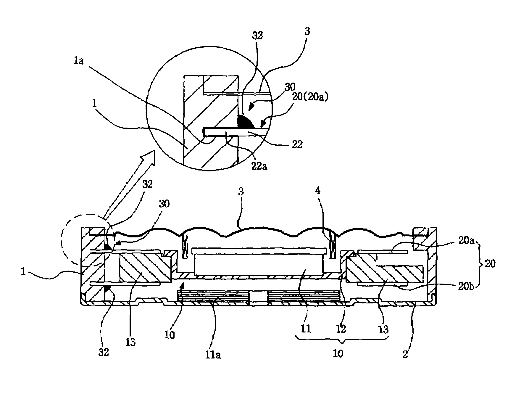
[0061]According to another aspect of the invention, a vibration speaker generating audio sound and vibration includes a case containing a vibration plate disposed on an upper portion of the case to generate the audio sound, and having a plurality of grooves formed on an inside of the case, a coil having a side portion coupled to the vibration plate to generate an electromagnetic force, a vibration unit disposed adjacent to the coil, having a magnet with opposite polarities, having a yoke attached to the magnet to form a magnetic circuit, and generating the vibration having an actual resonance frequency, and an elastic member elastically supporting the vibration unit to cause the vibration unit to generate the actual resonance frequency, having a plurality of arms extended in an outside circumference, and having protrusions formed on the respective arms to be inserted into respective grooves, and having a cutout portion formed on at least one of the arms to change strength of the elastic member to adjust the actual resonance frequency of the vibration unit.
[0064]It is yet possible that the vibration unit includes a weight disposed on an outside of the yoke to increase a mass of the vibration unit to increase a vibration efficiency of the vibration unit.

Problems solved by technology

However, it is a technical limitation in minimizing a size of the vibration motor depending on a trend of a slim mobile telecommunication terminal.
According to a current technology to make the steel plate, it is impossible to make a perfectly uniform steel plate.
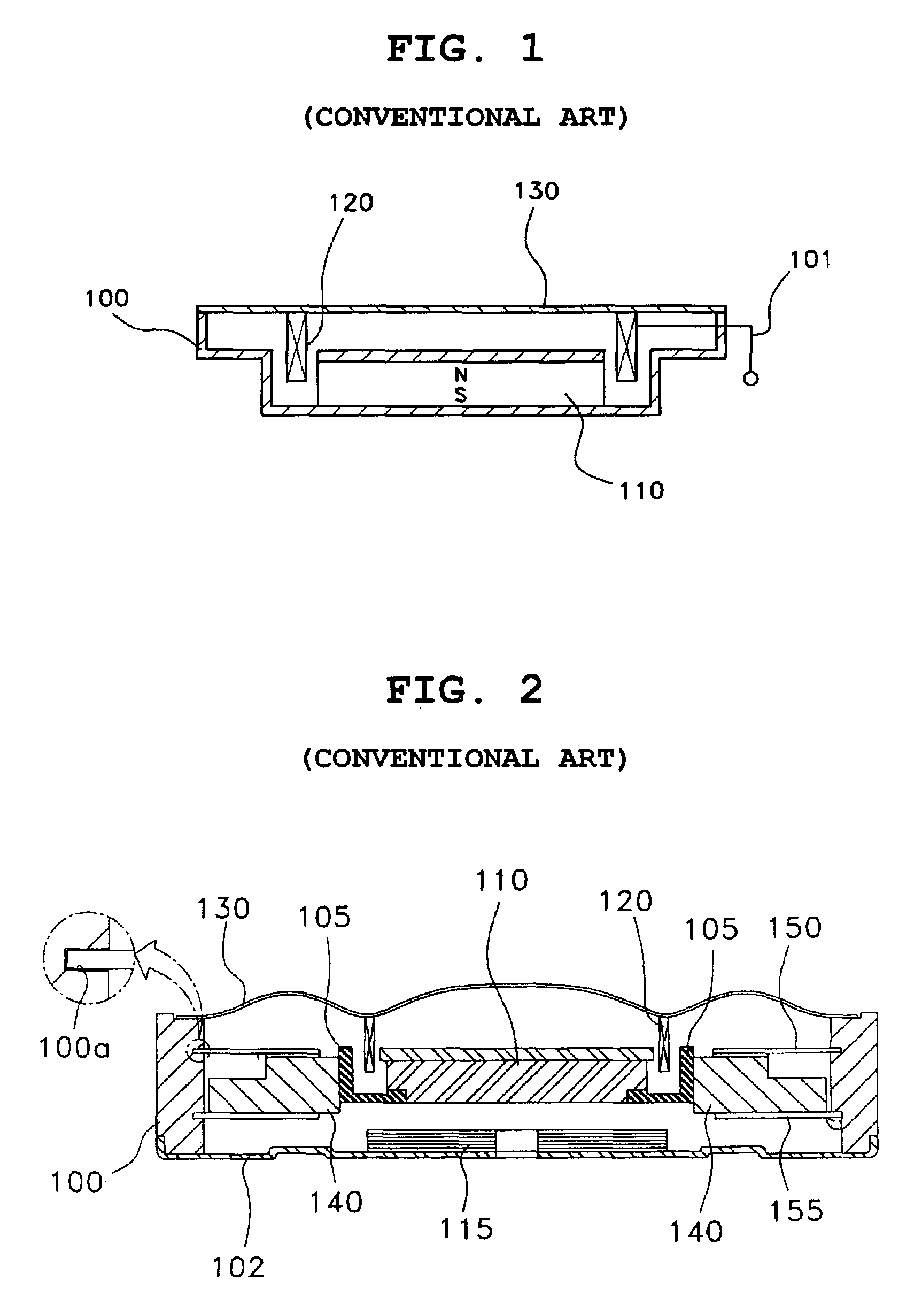
It is also impossible to avoid the difference in forming the plate springs 150, 155 due to a physical limitation.
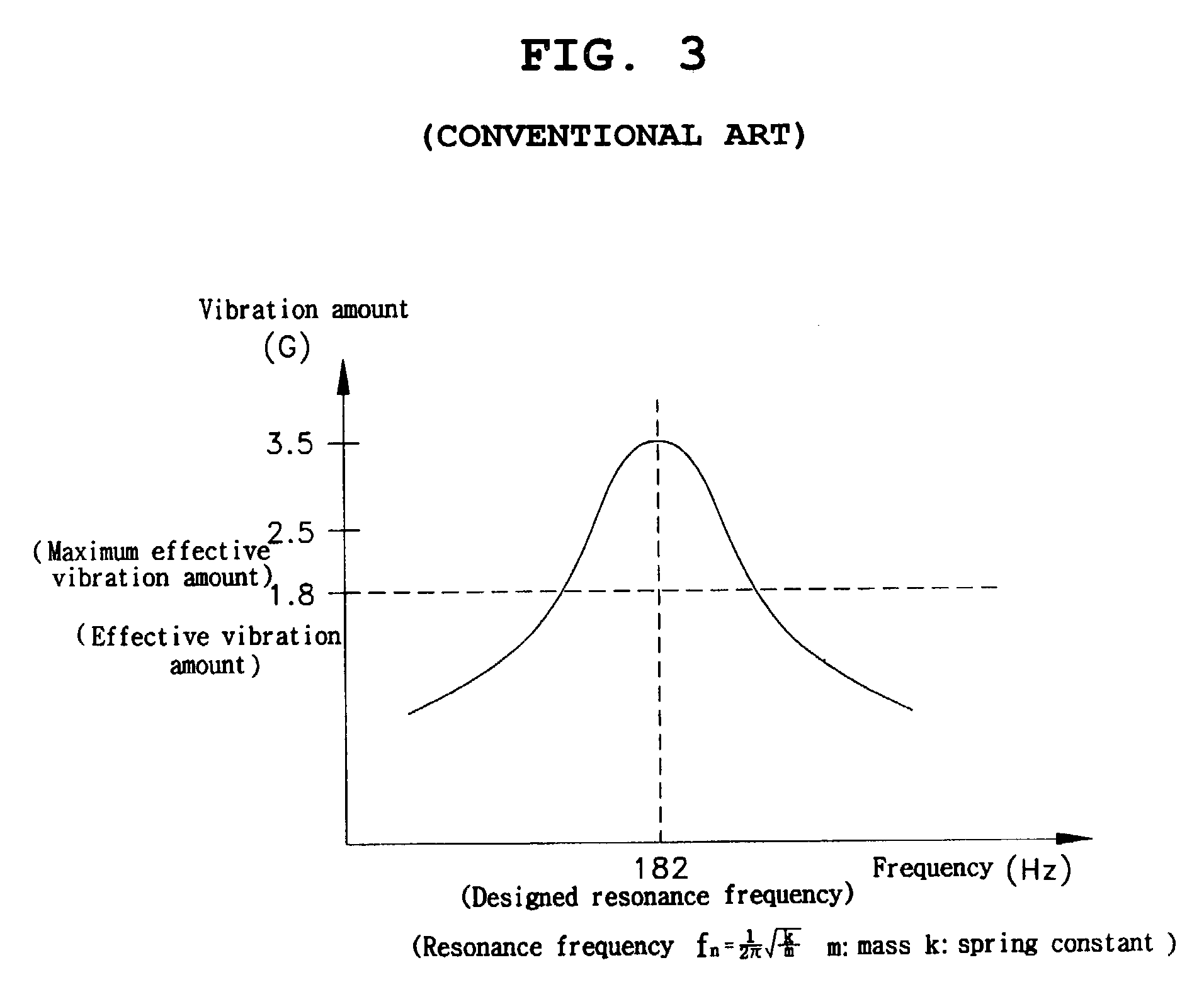
As a result, the manufactured vibration speaker becomes a defected speaker having lower vibration characteristics and a lower or higher resonance frequency with respect to the designed resonance frequency.
However, a manufacturing cost of the vibration speaker increases in proportion to an increase of a parts manufacturing cost if the manufacturing process of the parts is strictly managed to maintain the strength of the parts and the plate springs 150, 155 uniform.
However, it is impossible to technically manage the uniform thickness of 1˜2 mm in the plate springs 150, 155.
Thus, the vibration speaker cannot generate a desirable vibration operation, and a vibration sensitivity of the vibration speaker deteriorates.
The conventional vibration speaker is disadvantageous in that an effective space is limited for the vibrator to move upward and downward since the vibration speaker becomes slim, an unstable vibration occurs due to contact between the vibrator and lower and upper surfaces of the case 100, thereby generating noise and reducing a life-span of the vibration speaker.

Method used


Image

  • Resonance frequency correction method and vibration speaker
  • Resonance frequency correction method and vibration speaker
  • Resonance frequency correction method and vibration speaker

Examples


Embodiment Construction

[0081]Reference will now be made in detail to the present preferred embodiments of the present invention, examples of which are illustrated in the accompanying drawings, wherein like reference numerals refer to the like elements throughout. The embodiments are described below in order to explain the present invention by reference to the figures.

[0082]Hereinafter, a vibration speaker according to an embodiment of the present invention will be described in conjunction with the reformed drawings.

[0083]FIG. 4 is a plan view showing an elastic member 20 having spring constant determining portion and mounted on the vibration speaker. The elastic number is a plate type spring.

[0084]As shown in FIG. 4, the elastic member is formed in a circular changed plate and has a plurality of arms 22, 23, 24 with a plurality of protrusions 22a, 23a, 24a formed on an outer circumference of the circular shaped plate and inserted into a groove formed on an inside of a case of the vibration speaker which w...


PUM


Abstract

A method of correcting a resonance frequency in a vibration speaker generating acoustic sound and vibration includes adjusting the actual resonance frequency to a higher resonance frequency by limiting a predetermined portion of an elastic member installed in a case to an inside of the case to increase the resonance frequency when the actual resonance frequency is not identical to nor less than the desired resonance frequency, thereby adjusting an actual resonance frequency to be identical to a desired resonance frequency, and adjusting the actual resonance frequency to a lower resonance frequency by cutting off another predetermined portion of the elastic member to decrease the resonance frequency when the actual resonance frequency is not identical to nor greater than the desired resonance frequency, thereby adjusting an actual resonance frequency to be identical to a desired resonance frequency. In the vibration speaker, the actual resonance frequency is corrected to the desired resonance frequency, thereby reducing a defect of the vibration speaker.

Description

BACKGROUND OF THE INVENTION[0001]1. Field of the Invention[0002]The present invention relates to a vibration speaker mounted in a communication system generating acoustic sound and vibration, and more particularly, to a vibration speaker and a method of changing a spring strength of an elastic member to adjust an actual resonance frequency to a designed resonance frequency and to provide a stable vibration characteristic to the vibration speaker.[0003]2. Description of the Related Art[0004]FIG. 1 is a cross-sectional view of a conventional micro speaker used in a mobile (portable) communication terminal. The micro speaker includes a case 100 having an internal space, a magnet 110 and a voice coil 120 mounted in the case 100, and a vibration plate 130 generating audio sound.[0005]In the speaker, a current of a high frequency flows from an external source to the voice coil 120 through a lead line 101 to a magnetic field between the voice coil 120 and the magnet 110. The magnetic field...

Claims


Application Information

Patent Timeline
Patent Type & Authority Patents(United States)
IPC IPC(8): H04R25/00H04R1/22H04R1/28H04R9/10H04R11/06
CPCH04R1/225H04R9/10H04R2400/07H04R2400/03H04R11/06
Inventor CHUNG, SEUK HWAN
Owner SAMSUNG ELECTRO MECHANICS CO LTD
Why Eureka
Try Eureka