Changing pad cover

a changing pad and cover technology, applied in the direction of sofas, contraceptives, upholstery, etc., can solve the problems of shortening the life of the pad, affecting the laundry workload of the new family,

Inactive Publication Date: 2006-02-28
WILSON MARY BESS
View PDF24 Cites 38 Cited by
  • Summary
  • Abstract
  • Description
  • Claims
  • Application Information

AI Technical Summary

Benefits of technology

[0008]Each vinylized layer preferably comprises a clear vinyl (polymeric) layer, that is, a substantially waterproof or impermeable layer, which is superimposed or in a face-to-face relationship with an underlying material, preferably made from a fabric. Alternatively, the upper portion only of the cover may have the impermeable layer or the combination of the upper portion and the side portions may have the impermeable layer. The underlying material has decorative visual art indicia depicted on it so as to be visually observable through the vinyl layer. The underlying material when made from a fabric material may be made from cotton, polyester, rayon or combinations of these materials. The underlying material may also be made from a polymeric material. The top portion of the cover may also include an opening in which a safety belt-like strap protrudes from the pad itself to prevent the baby from rolling off the changing table / pad. Alternatively, the top portion of the cover itself may include a safety belt-like strap to prevent the baby from rolling off the changing table / pad.

Problems solved by technology

This creates a large laundry workload for the new family, who must typically purchase at least three covers to rotate onto the pad.
These stitch lines often crack thereby shortening the life of the pad unless it is repairable.

Method used


Image

  • Changing pad cover
  • Changing pad cover
  • Changing pad cover

Examples


Embodiment Construction

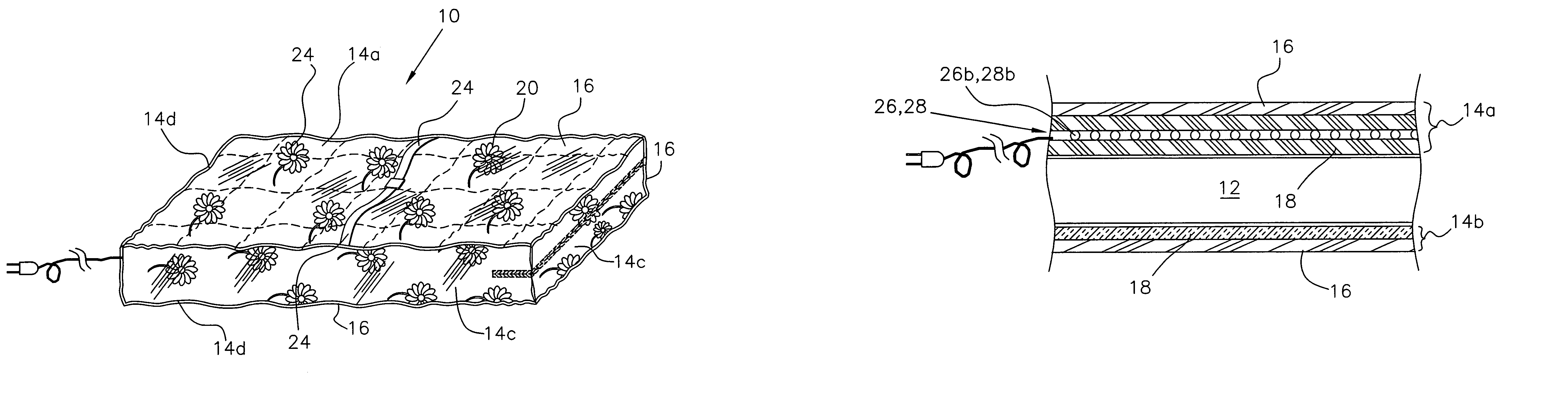
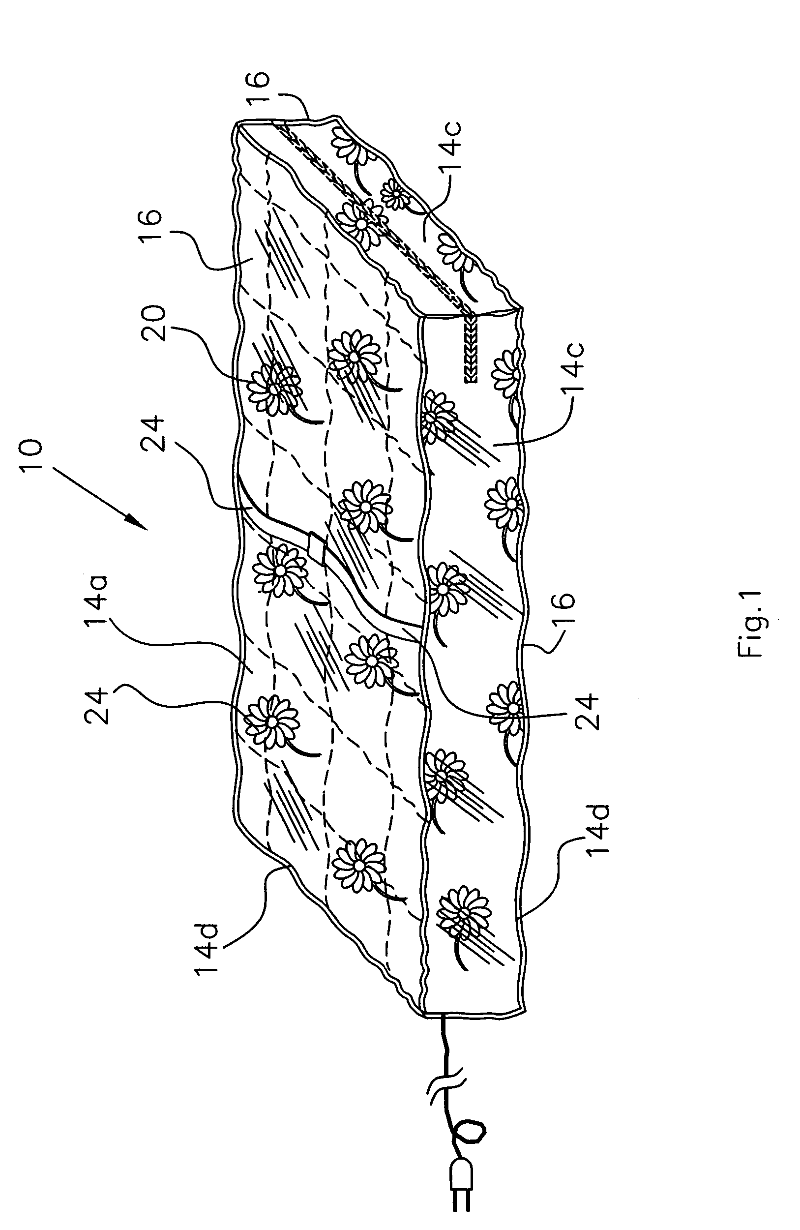
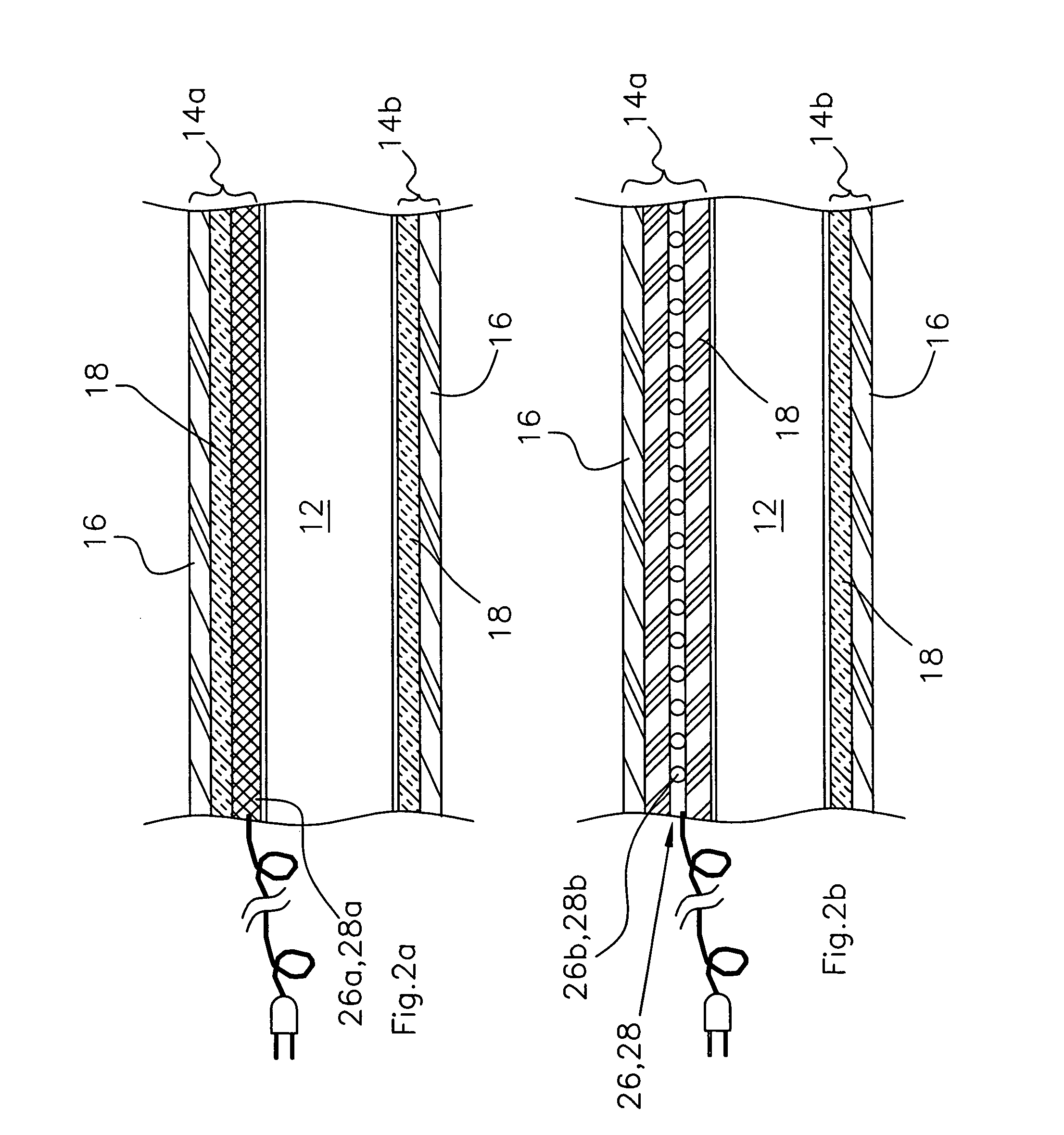
[0021]Referring now to the drawings, FIG. 1 discloses a conceptual ready for use embodiment of the present invention, which is a changing pad cover, depicted generally as 10. Typical pads 12 and their respective shapes contemplated to be covered by the present invention 10 are depicted in FIGS. 4a–4c.

[0022]As further conceptually depicted in FIGS. 2a–2b and 3a–3c, the invention is a changing pad cover 10, which includes a generally rectangular-shaped upper portion 14a and a spaced-apart lower portion 14b with upright side portions 14c. The upper portion and the lower portions 14a,14b are connected to the respective upright side portions 14c along respective perimeter edges 14d thereof. The connection means can be done in a number of ways known in the art, including stitching, adhesive joints, or combinations of adhesive and stitching as appropriate. It is preferable that some form of blind stitching be utilized to minimize any soil or contaminant trap areas along the perimeter edge...


PUM


Abstract

A changing pad cover having two generally parallel vinylized / fabric layers spaced-apart and four upright sides connecting each spaced-apart layer. One or both ends of the cover may have its raised sides contoured-shaped on its upper edge to allow for the upper layer of the cover to conform to the contoured upper surface shape of the pad. The cover is secured at one end with a closure device such as a hook and loop fastener. The vinylized layer comprises a clear liquid impermeable layer, which is superimposed in a face-to-face relationship with an underlying fabric material. The fabric material has decorative visual art indicia depicted on the fabric material. The cover may optionally include a heating pad and / or a vibrating pad in an underlying relationship to the fabric material of the upper portion of the cover or integral to the fabric material. An alternative embodiment includes the top and sides of the cover only.

Description

FIELD OF THE INVENTION[0001]The invention relates to sanitary and decorative changing pad covers for use when changing children's diapers.BACKGROUND OF THE INVENTION[0002]The current apparatus used to change diapers typically consists of a foam core covered with a thin white plastic film that is unattractive and can crack over time. FIGS. 4a–4c show representative shapes of such pads. It is designed to work in conjunction with a changing pad cover (in most cases, terry-cloth), which provides the baby with a soft surface. The colors are usually selected in colors of the nursery, which is a major contemplated user of the present invention.[0003]The pad must be removed immediately upon being soiled to prevent stains and / or contamination by urine or feces and unpleasant odors. This creates a large laundry workload for the new family, who must typically purchase at least three covers to rotate onto the pad.[0004]The present invention discussed below eliminates the need for such laundry w...

Claims


Application Information

Patent Timeline
Patent Type & Authority Patents(United States)
IPC IPC(8): A47G9/00A47D15/00A47D5/00A47G9/04
CPCA47C21/048A47D15/003A47D5/00Y10S5/915
Inventor WILSON, MARY BESS
Owner WILSON MARY BESS
Why Eureka
Try Eureka