Gyro wave activated power generator and a wave suppressor using the power generator

Inactive Publication Date: 2006-02-28
KANKI HIROSHI
View PDF8 Cites 17 Cited by
  • Summary
  • Abstract
  • Description
  • Claims
  • Application Information

AI Technical Summary

Benefits of technology

[0009]The means of the technical solution offered by the present invention is a gyro wave-activated power generator that comprises a floating body, a control moment gyro supported on said floating body, and a p

Problems solved by technology

However, the production of solar panels involves significant costs.
Wave power generation is being actively studied in Japan but the technology has not yet reached commercial levels.
Wave-activated power generators using fluids, such as those mentioned above, a

Method used


Image

  • Gyro wave activated power generator and a wave suppressor using the power generator
  • Gyro wave activated power generator and a wave suppressor using the power generator
  • Gyro wave activated power generator and a wave suppressor using the power generator

Examples


Embodiment Construction

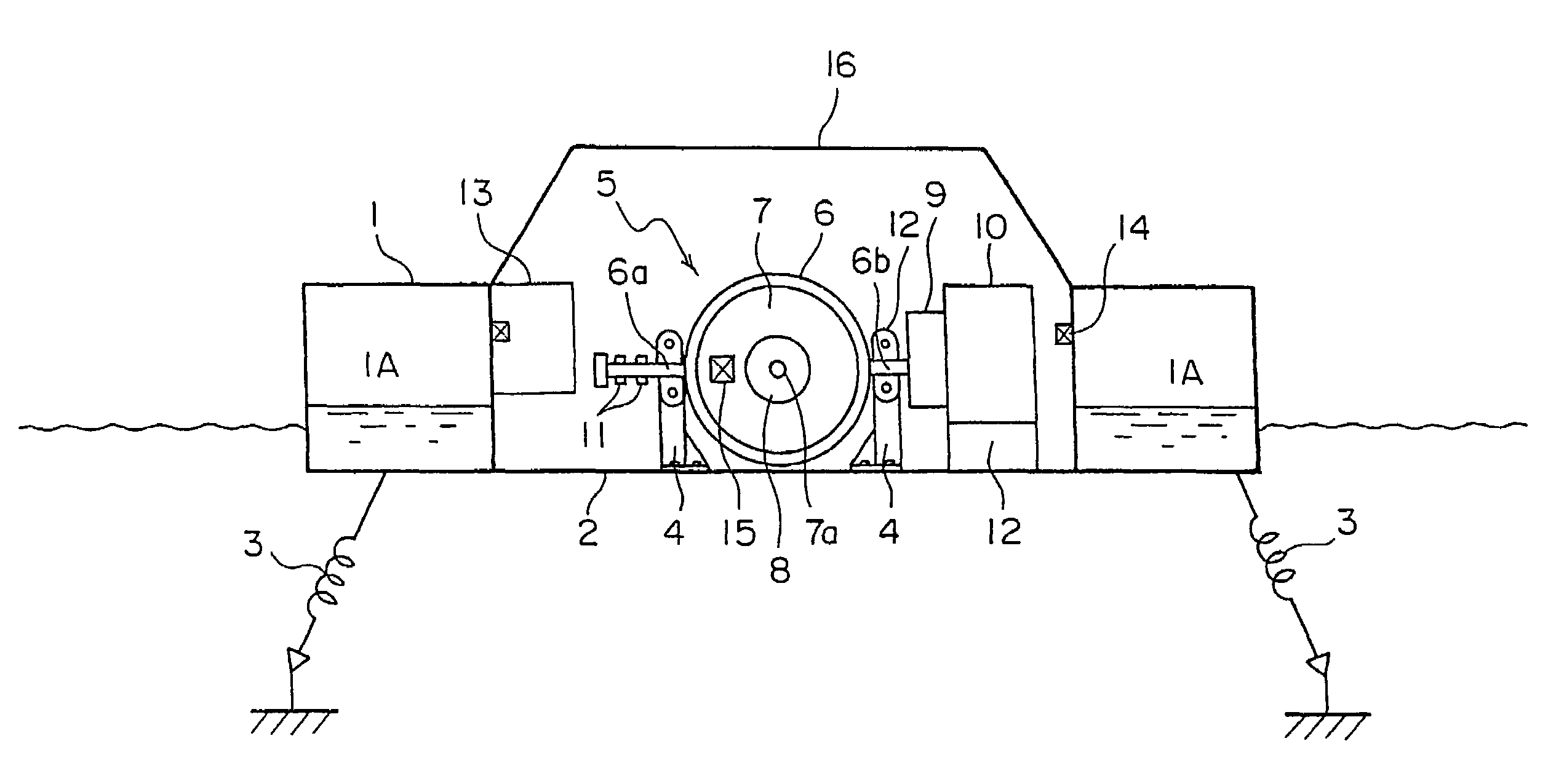
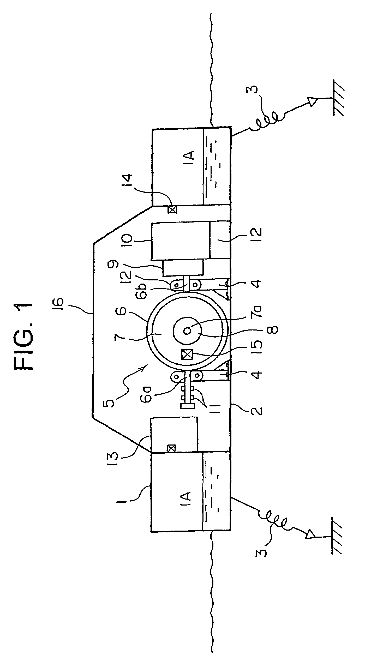
[0020]The gyro wave-activated power generator of the present invention, which comprises a control moment gyro, a power generator, and a controller, is described below referring to the attached drawings.

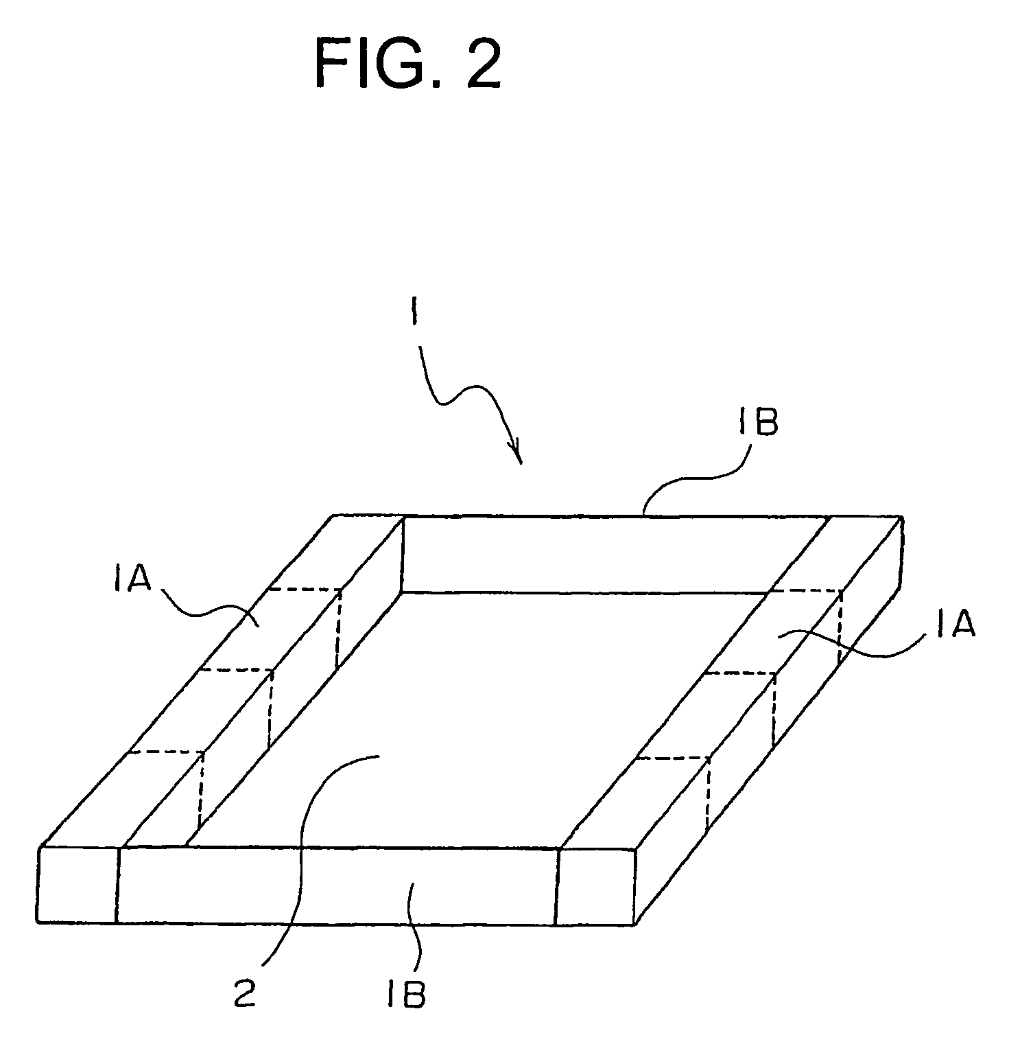
[0021]FIG. 1 is a cross-sectional view of the first working example of the power generator of the present invention. FIG. 2 is an oblique view of the floating body used in the present invention. FIG. 3 is the control block diagram. FIG. 4 is the plan of a typical layout of an array of control moment gyros of the present invention.

[0022]In FIG. 1, the main floating body (1), roughly square in shape, comprises two floating sub-bodies (1A) which are connected by two members (1B). The control moment gyro power generator, which is described later, is positioned at the center of the bottom (2) of said square floating body. The main floating body (1) is fixed to the sea bottom with anchors (3). The main floating body (1) may not necessarily be square in shape but may also be of any other sha...


PUM


Abstract

A gyro wave-activated power generator utilizing wave energy which has, as a component, a control moment gyro, and which comprises a floating body (1), a control moment gyro (5) supported by the floating body, and a power generator (10) connected to the gimbal shaft of the gyro through a gearing to increase speed(9), and is characterized by the gimbal (6) of the gyro being rotated by the movement of the floating body by wave energy to drive the power generator (10) for power generation.

Description

FIELD OF TECHNOLOGY[0001]The present invention relates to a gyro wave-activated power generator utilizing wave energy which has, as a component, a control moment gyro.BACKGROUND ART[0002]Global environmental problems including global warming are recently being seriously studied throughout the world. It is necessary to actively promote the use of clean natural energy.[0003]The use of natural energy typically includes photovoltaic power generation, wind power generation, and wave-activated power generation. Photovoltaic and wind power generation are commercially available. However, the production of solar panels involves significant costs. In Japan, where earthquakes and typhoons frequently occur, wind power generation plants must be constructed with extra strength. Vast land areas are required to construct large-scale wind power generation farms.[0004]As Japan is an island nation surrounded by the sea on all sides, wave power generation is a promising energy source. Wave power genera...

Claims


Application Information

Patent Timeline
IPC IPC(8): F02B3/06F02B9/08F03B13/14F03B13/16F16D31/02F03B13/18F03B13/20
CPCF03B13/18F03B13/20Y10S415/916F05B2240/93Y02E10/38F05B2220/706Y02E10/30F05B2250/44
Inventor KANKI, HIROSHI
Owner KANKI HIROSHI
Why Eureka
Try Eureka