V-type multiple-cylinder air intake device

a technology of air intake device and multiple cylinders, which is applied in the direction of combustion engine, combustion air/fuel air treatment, charge feed system, etc., can solve the problems of inability to use the method in a straightforward manner, the volume of the collector is reduced, and the output of the engine to decline, so as to eliminate residual resonance and reduce the volume of the collector

Inactive Publication Date: 2006-02-28
NISSAN MOTOR CO LTD
View PDF15 Cites 35 Cited by
  • Summary
  • Abstract
  • Description
  • Claims
  • Application Information

AI Technical Summary

Benefits of technology

[0008]The present invention was conceived in view of this need. One object of the present invention is to provide an air intake device intended for a V-type multiple cylinder engine that have independent collectors on the left and right banks of the engine, wherein the air intake device utilizes a comparatively simple design to prevent in an effective manner a decline in the output of the engine in regions of medium to high engine speeds without causing the collector volume to increase.

Problems solved by technology

It has been discovered that there are times, when it is necessary to reduce the volume of the collectors due to layout constraints.
However, when the engine is operating in medium to high rotational speed regions, this resonance becomes counter-effective residual resonance and causes the output of the engine to decline.
However, this method cannot always be utilized in a straightforward manner because it is necessary to provide the communication pipe with a comparatively large cross sectional area.
If the collector volume has been reduced due to layout constraints, the large cross sectional area of the communication pipe will be counteractive because it will result in increasing the volume of the collector (or the space required for the collector).

Method used


Image

  • V-type multiple-cylinder air intake device
  • V-type multiple-cylinder air intake device
  • V-type multiple-cylinder air intake device

Examples


first embodiment

[0035]With the first embodiment, the output (volumetric efficiency) can be improved due to the resonance effect when the engine is operating in low rotational speed regions. Meanwhile, effect of residual resonance is suppressed and declination of engine output is prevented when the engine is operating in medium to high rotational speed regions. Moreover, the engine output (volumetric efficiency) can be improved at medium to high engine speeds by designing the branch pipes (2L and 2R) in such a manner as to take advantage of the inertia effect.

[0036]However, it is difficult to obtain a sufficient inertia effect at engine speeds ranging from the low speed region to the high speed region by merely tweaking the design of the first branches. Generally speaking, it is necessary to increase the length of the air intake pipes running from the collectors to the cylinders in order to set the optimum rotational speed for the inertia effect to a low rotational speed. Meanwhile, it is necessary ...

second embodiment

[0043]The operation of the second embodiment will now be described.

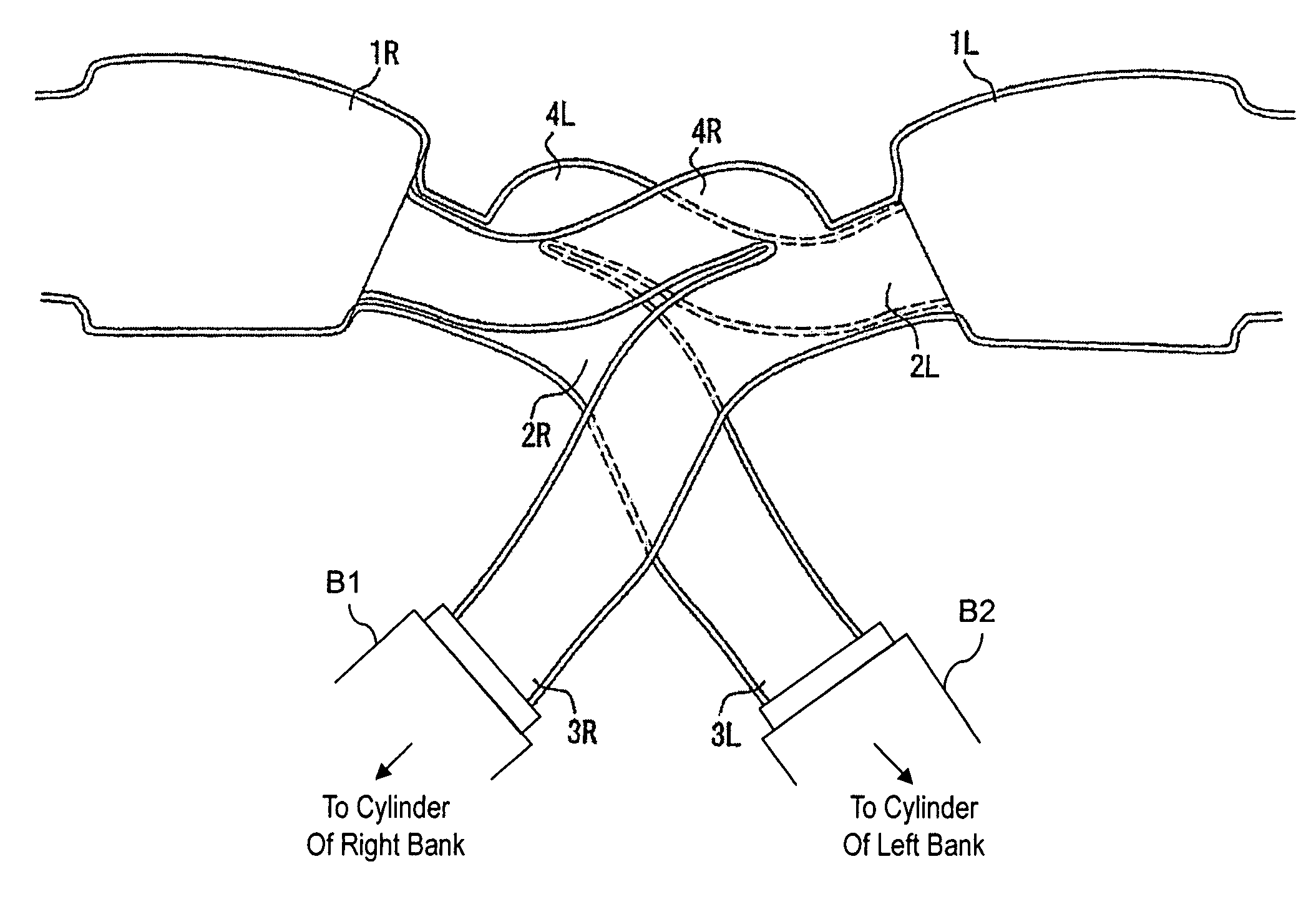
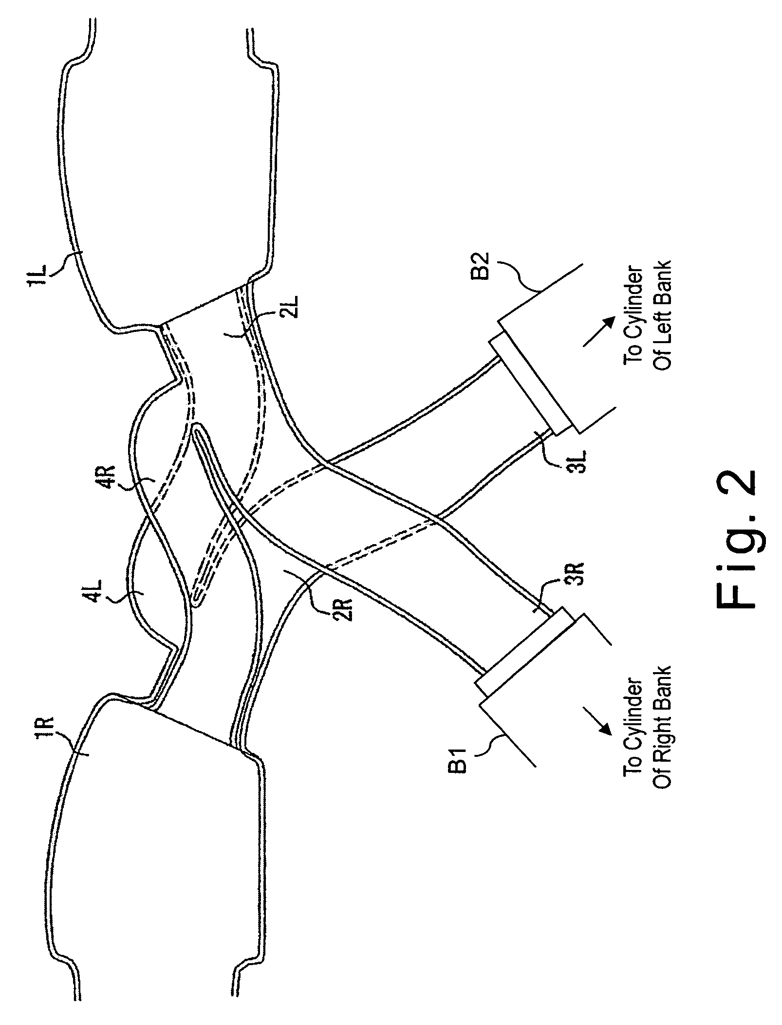
[0044]The ON / OFF valves 5L and 5R are closed when the engine is operating in a low rotational speed region (closed positions of the ON / OFF valves 5L and 5R are indicated with solid-line sketch in FIG. 3). When the ON / OFF valves 5L are closed, the intake air flows from the right collector 1R to the intake ports 3R of the right bank B1 through the second crossover passages 4R and the first branch pipes 2L, as shown in FIG. 4. When the ON / OFF valves 5R are closed, the intake air flows from the left collector 1L to the intake ports 3L of the left bank B2 through the first crossover passages 4L and the second branch pipes 2R, as shown in FIG. 3.

[0045]By closing the valves 5L and 5R, the effective length of the intake pipes from the collectors 1L and 1R to the cylinders is lengthened and the optimum rotational speed for the inertia effect is shifted to a lower rotational speed. As a result, the volumetric efficiency can be...

third embodiment

[0056]the present invention will now be described with reference to FIGS. 7 and 8. The third embodiment is different from the second embodiment in that the ON / OFF valves 5L and 5R are provided inside the first and second branch pipes 2L and 2R at positions upstream of the portions where the first and second branch pipes 2L and 2R merge with the crossover passages 4R and 4L (i.e., at positions further upstream relative to the flow of the intake air). Another difference is that the portion of each first branch pipe 2L and 2R upstream of the respective ON / OFF valve 5L and 5R (i.e., the portion of each first branch pipe 2L that is closer to the left collector 1L and the portion of each second branch pipe 4R that is closer to the right collector 1R) has a larger cross sectional area than the portion of each first branch pipe 2L and 2R downstream of the respective ON / OFF valve 5L and 5R (i.e., the portion of each first branch pipe 2L that is closer to the intake port 3R of the right bank ...


PUM


Abstract

A V-type multiple cylinder air intake is being configured to improve the volumetric efficiency by utilizing the resonance effect while also eliminating the adverse influence of the resonance effect (residual resonance) when the engine is operating in regions of medium to high rotational speeds. The V-type multiple-cylinder air intake device has two collectors with one arranged on each bank of the V-type multiple-cylinder engine; a plurality of branch pipes extending from the collectors to a respective intake port of an opposite bank; and a plurality of crossover passages extending from the collectors to a respective branch pipes extending from the collector of the opposite bank.

Description

BACKGROUND OF THE INVENTION[0001]1. Field of the Invention[0002]The present invention generally relates to a V-type multiple-cylinder air intake device.[0003]2. Background Information[0004]One example of a V-type multiple-cylinder air intake device is disclosed in Japanese Laid-Open Patent Publication No. 11-294171. The air intake device described in that publication is provided with a collector having a first volume chamber in a middle section thereof, a pair of second volume chambers arranged on both sides of the first volume chamber, and ON / OFF valves configured and arranged to connect and disconnect the second volume chambers to and from the first volume chamber. When the engine is operating in a low rotational speed region, the ON / OFF valves are closed so as to separate the left and right second volume chambers into independent chambers. As a result, the volumetric efficiency is improved by a resonance effect. When the engine is operating in a high rotational speed region, the ...

Claims


Application Information

Patent Timeline
Patent Type & Authority Patents(United States)
IPC IPC(8): F02M35/10F02B27/02F02M35/116
CPCF02B27/02F02M35/10045F02M35/10072F02M35/10131F02M35/10255F02M35/116F02M35/10118F02B27/0284Y02T10/14Y02T10/146F02B27/0221F02B27/0252F02B27/0273F02B27/0278Y02T10/12
Inventor KUNUGI, TAKASHISAKURAGI, SHIGERUSASAKI, TORUFUJITA, HIDEHIRO
Owner NISSAN MOTOR CO LTD
Why Eureka
Try Eureka