Laryngeal mask with large-bore gastric drainage

a gastric contents and laryngeal technology, applied in the field of medicine, can solve the problems of difficult installation in patients of a laryngeal mask having a large-bore gastric contents drainage tube, reducing the bulk and stiffness of the lma structure, and facilitating the insertion of the lma

Inactive Publication Date: 2006-02-28
TELEFLEX LIFE SCI PTE LTD
View PDF108 Cites 77 Cited by
  • Summary
  • Abstract
  • Description
  • Claims
  • Application Information

AI Technical Summary

Benefits of technology

[0007]It is an object of the invention to provide a laryngeal mask for humans and other mammals which offers ease of insertion, and in addition accommodates a large-bore “gastro-tube”, typically larger than the airway tube(s) of the device and up to 15-mm inside diameter in adult human sizes. In the event of reflux of gastric contents, the larger-bore tube permits substantially unobstructed passing of such matter from the oesophagus to the exterior of the mouth. Also, a large-bore drainage tube may be used as a conduit for other applications such as temperature monitoring, endoscopy, suction or alimentation, which may be accommodated through a gastro-tube.

Problems solved by technology

Providing a laryngeal mask which retains the ease of use of the original but also has a tube for drainage of gastric contents, may be difficult.
Additionally, installation in a patient of a laryngeal mask having a large-bore gastric drainage tube (e.g., as described in U.S. Pat. No. 5,241,956) may be more difficult as compared to a standard LMA device.
Also, while a laryngeal mask having a smaller-bore gastric drainage tube is typically easier to install in a patient, the flow capacity of such a drainage tube for gastric contents (resulting, for example, from vomiting) may be more limited.
Moreover, a laryngeal mask having a smaller-bore gastric drainage tube may not be able to accommodate a large stomach tube (e.g., of greater than 6 mm OD).

Method used


Image

  • Laryngeal mask with large-bore gastric drainage
  • Laryngeal mask with large-bore gastric drainage
  • Laryngeal mask with large-bore gastric drainage

Examples


Embodiment Construction

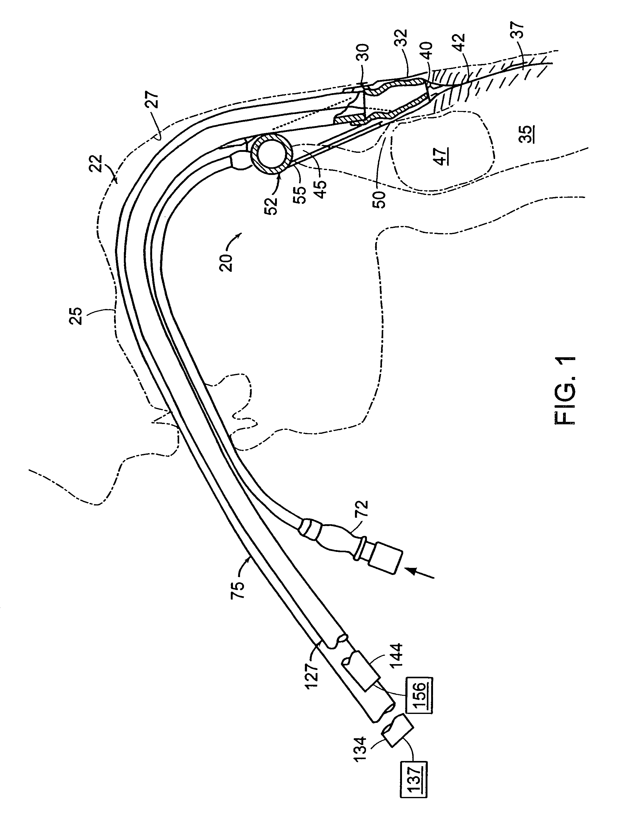
[0034]A laryngeal-mask airway system embodying the present invention is designated generally by the reference numeral 20 in FIG. 1.

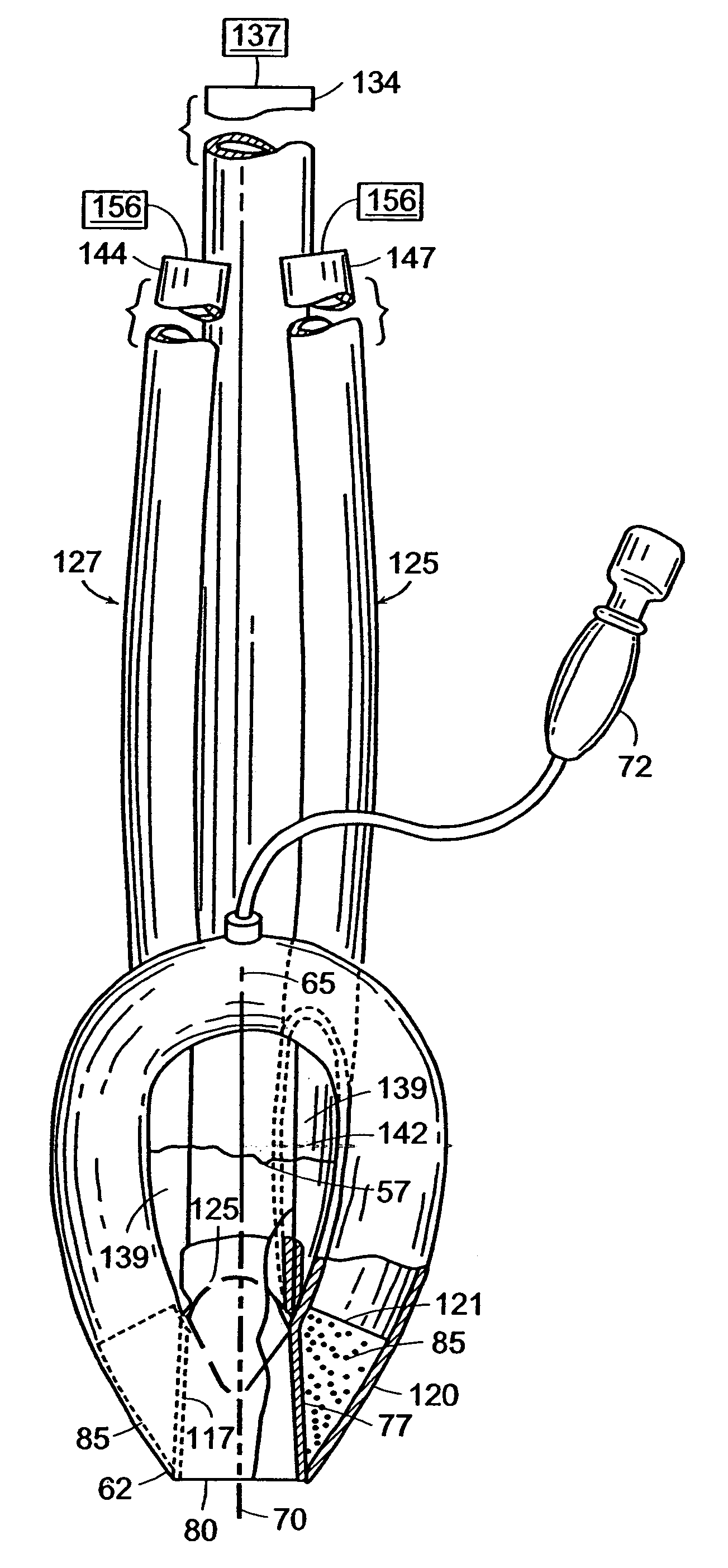
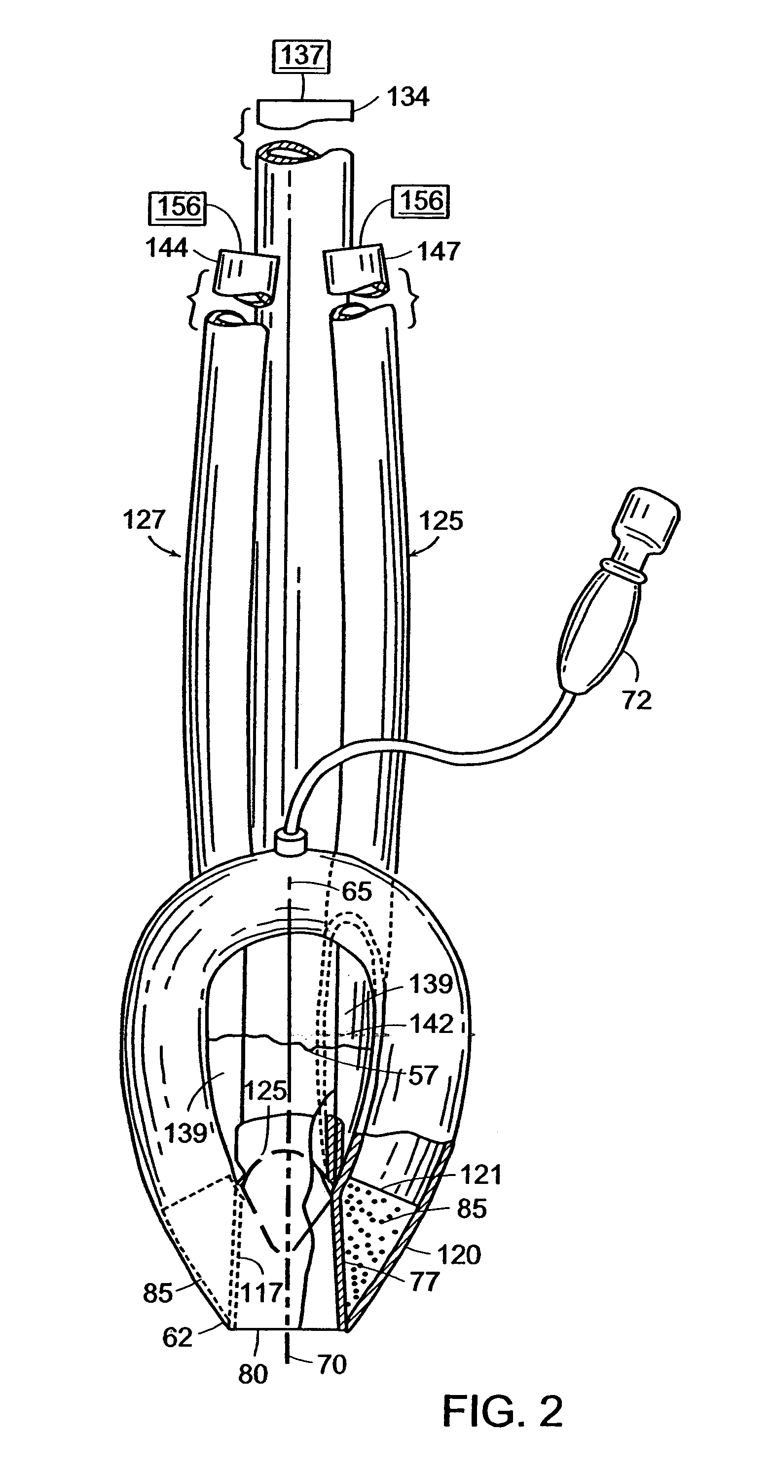
[0035]As discussed in more detail below, airway system 20 includes a mask structure 52 at the distal ends of a flexible gastro-tube 75 and a pair of airway tubes 125, 127. The gastro-tube and airway tubes conform to the curvature of the patient's airway when flexed. The proximal end 134 of gastro-tube 75 may be connected to a conventional, external gastro suction apparatus 137. The proximal tube 144, 147 of airway tubes may be connected to a conventional ventilating system 156 external of the patient. Air inflation / deflation tube 72 also passes from external of the patient and through the patient airway to the mask structure.

[0036]Airway system 20 is inserted into anatomical airway 22 the upper surface of which is bounded by hard and soft palates 25, 27. The mask 52 of airway system 20 is lodged in pharynx 30 of anatomical airway 22 at the base of hypoph...


PUM


Abstract

An artificial airway device for use in unconscious patients comprises a laryngo-pharyngeal mask including an expandable masking ring. The expandable mask sealingly surrounds the laryngeal inlet when expanded to obstruct communication between the laryngeal inlet and oesophagus. One or more airway tubes connected to the mask provide for fluid flow to a portion of the mask facing the laryngeal inlet when said mask sealingly surrounds the laryngeal inlet. A gastro-tube connected to the mask provides a fluid flow-path to the mask when the mask sealingly surrounds the laryngeal inlet. The distal end of the gastro tube passes through the masking ring at its narrower distal region where, when installed in a patient, it abuts against the oesophagus; and the distal portion of the gastro-tube flattens when the mask is deflated to facilitate smooth passage behind the larynx during insertion through the mouth and throat of the patient.

Description

CROSS REFERENCE TO RELATED APPLICATIONS[0001]This application is a continuation of application Ser. No. 10 / 684,048, filed Oct. 10, 2003, which is a continuation of application Ser. No. 09 / 413,970, filed Oct. 7, 1999, now U.S. Pat. No. 6,631,720.BACKGROUND OF THE INVENTION[0002]The present invention relates generally to medicine, and more particularly, to anesthesia, emergency medicine, intensive therapy, and veterinary medicine.[0003]The laryngeal mask airway (LMA) disclosed in U.S. Pat. No. 4,509,514 is an artificial airway device designed to facilitate ventilation of an unconscious patient, and is used in over 80 countries. An unconscious patient, undergoing ventilation whether spontaneous or controlled via an LMA, may regurgitate or vomit gastric contents, as may happen if the stomach is not empty before such ventilation. Leakage of such gastric contents into the lungs should be prevented because it may be fatal. U.S. Pat. No. 5,241,956 describes modified laryngeal masks includin...

Claims


Application Information

Patent Timeline
Patent Type & Authority Patents(United States)
IPC IPC(8): A61M16/00A61M25/00A61M16/04A61M25/04
CPCA61M16/04A61M16/0415A61M16/0409A61M2210/0656A61M16/0431A61M16/0486
Inventor BRAIN, ARCHIBALD I. J.
Owner TELEFLEX LIFE SCI PTE LTD
Why Eureka
Try Eureka