Electric fence post installer

a technology for installing fence posts and fence posts, which is applied in mechanical machines/dredgers, manufacturing tools, forging/pressing/hammering apparatus, etc., can solve the problems of difficult to drive rods or fence posts into the ground, and the same is extremely complicated

Inactive Publication Date: 2006-02-28
VOICHOSKIE ROBERT R +1
View PDF13 Cites 23 Cited by
  • Summary
  • Abstract
  • Description
  • Claims
  • Application Information

AI Technical Summary

Benefits of technology

[0006]The electric fence post installer of this invention comprises a wheeled frame means having a forward end, a rearward end, and first and second sides. The wheeled frame means is pulled behind a truck, ATV, tractor, or other prime mover. A vertically disposed support member, having upper and lower ends, is secured at its lower end to the wheeled frame and has a horizontally disposed boom arm selectively rotatably secured to the upper end thereof which has inner and outer ends. The boom arm is selectively rotatably movably positioned with respect to the support member so that the boom arm may be moved from a transport position adjacent the wheeled frame means to an operative position outwardly of the wheeled frame means. The apparatus includes a first brake which selectively locks the boom arm in selected positions with respect to the support member. A pivot yoke is pivotally secured to the outer end of the boom arm about a horizontal axis and a vertical axis. A carousel support is selectively vertically movably secured to the pivot yoke and a vertically disposed carousel is selectively rotatably mounted on the carousel support. The apparatus of this invention also includes second and third brakes which selectively lock the carousel in a vertically disposed position or plumb condition prior

Problems solved by technology

The problem with the above method is that the task is time-consuming and many times the ground is frozen, which makes it difficult to drive the rods or fence posts into the ground.
Prior art devices have been provided for drilling post holes in the ground and then installing fence posts therein, but the same are extremely complicated and suffer from many disadvantages.
It is believed that the prior art devices, while possibly somewhat performing their intended functions on

Method used


Image

  • Electric fence post installer
  • Electric fence post installer
  • Electric fence post installer

Examples


Embodiment Construction

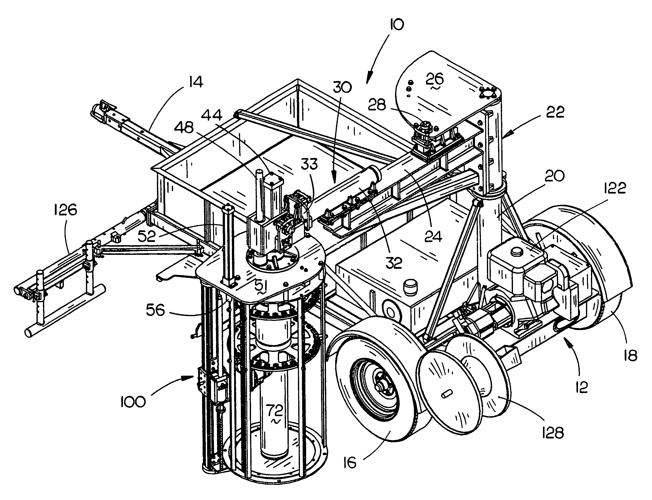
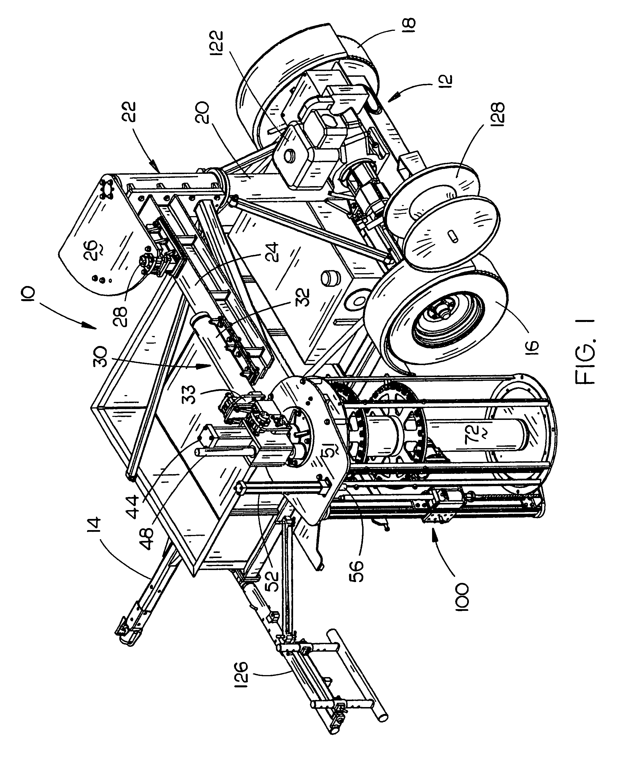
[0031]The electric fence post installer of this invention is referred to generally by the reference numeral 10 and is comprised of a wheeled frame means 12 which is adapted to be pulled or towed behind a prime mover such as a pickup truck, truck, ATV, tractor, or the like. The design of the installer 10 is such that it is easily moved from field location to field location and when used in a field, is stable and convenient to use. Wheeled frame means 12 includes a rear axle having wheels 16 and 18 mounted thereon. The forward end of wheeled frame means 12 includes a conventional hitch or tongue 14 thereon for connection to the prime mover. The numeral 20 refers to an upstanding support member which has its lower end secured to the wheeled frame means 12 and which has a tubular boom arm pivot 22 rotatably mounted on the upper end thereof. Boom arm pivot 22 may be manually rotated with respect to member 20 or may be rotated with respect thereto by a gear motor, hydraulic cylinder, etc....


PUM

PropertyMeasurementUnit
Structureaaaaaaaaaa
Transport propertiesaaaaaaaaaa

Abstract

An electric fence post installer comprising a wheeled frame having a first upstanding support extending upwardly therefrom. A generally horizontally disposed boom arm is rotatably mounted on the upper end of the first support and has a carousel support secured to the outer end thereof. A carousel is rotatably mounted, about a vertical axis, on the carousel support and is adapted to have a plurality of vertically disposed and radially spaced-apart electric fence posts supported thereon. A vertically disposed drill is mounted on the carousel support and is adapted to be rotated and moved downwardly with respect to the carousel support to drill a post hole in the ground. After the post hole has been drilled, a fence post is moved from the carousel to a position over the post hole and then is forced downwardly into the post hole. The installer includes means for ensuring that the post hole will be drilled substantially vertically into the ground.

Description

BACKGROUND OF THE INVENTION[0001]1. Field of the Invention[0002]This invention relates to an electric fence post installer and more particularly to an apparatus which is pulled behind a truck, ATV, tractor, or the like, and which includes means for drilling a post hole in the ground and then driving an electric fence post downwardly into the post hole. More particularly, this invention relates to a post hole drilling and post-driving machine wherein the electric fence posts are supported on a rotatable carousel in a radially spaced-apart fashion to facilitate the installation of the electric fence posts in the drilled post holes.[0003]2. Description of the Related Art[0004]When a farmer or rancher desires to permit his or her cattle to graze in a harvested cornfield or the like, the farmer drives or inserts electric fence posts into the ground at predetermined intervals and then extends an electric fence wire therebetween which is supported thereon by insulators attached to the fenc...

Claims


Application Information

Patent Timeline
IPC IPC(8): B21J7/02
CPCE04H17/263
Inventor VOICHOSKIE, ROBERT R.KATHMAN, WILLIAM J.
Owner VOICHOSKIE ROBERT R
Why Eureka
Try Eureka